Team:Cambridge-JIC/Tech Specs
Technical Specifications: Fact File
Some facts about OpenScope that we think you should know when you get started.
Optics
 The imaging system of OpenScope is based on a Raspberry Pi camera. Inverting the lens of the camera converts it into a microscope objective. For a detailed explanation, see the PDF below. With the Raspberry Pi Camera a resolution of 4 μm was achieved, but subsequently sub-micron resolution was reached with a commercially available 'ball lens' (from Comar Optics). OpenScope's objective holder is 3D-printed - like the rest of the chassis - and the spacing between the CCD and the lens in it was optimised for the lenses we used. However, this is an easily modifiable parameter in our .scad design files, which means that anyone can adapt the objective they use for the magnification, field of view, and resolution they need.
Multiple Microscopy Modes
 OpenScope supports three different modes of microscopy:
Brightfield: in this simplest setup, the sample is illuminated with a white LED from below
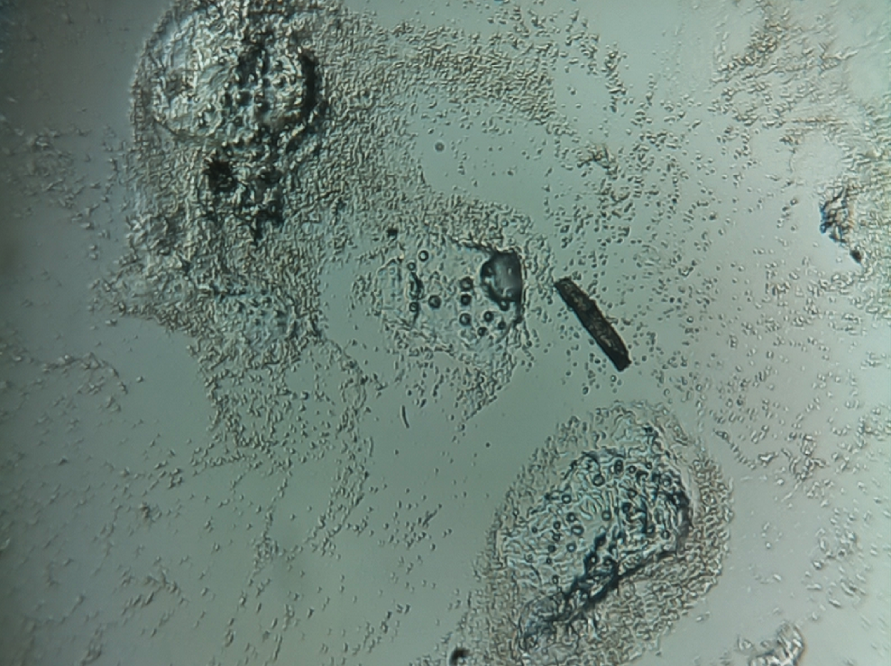
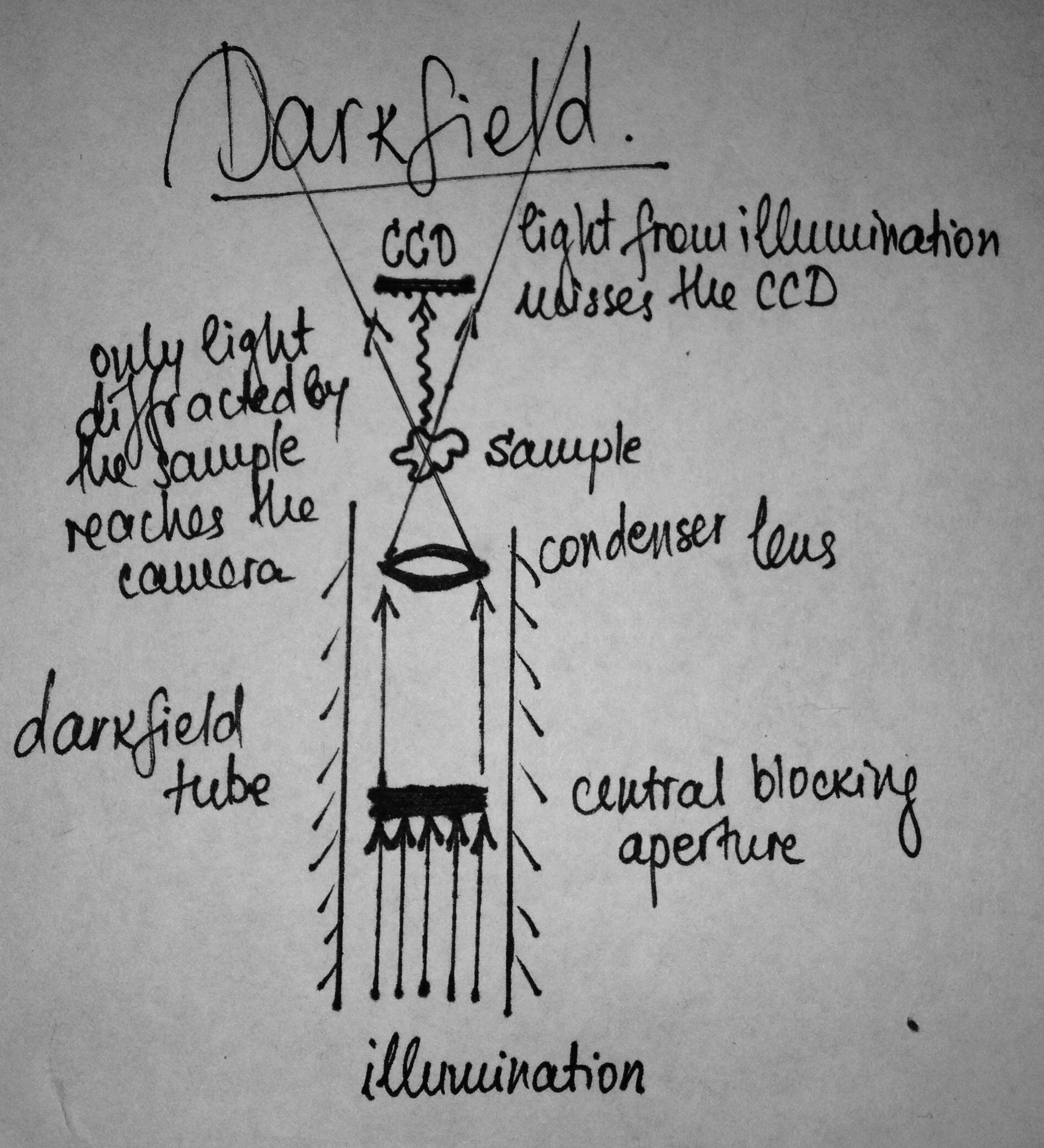
Darkfield: this mode requires mounting of a 3D-printed darkfield tube underneath the stage (for a brief explanation on how darkfield works, see the diagram on the right)
Fluorescence: for this mode, we have carefully developed the epi-cube, which houses the camera CCD, the lens, the 3 filters required, and the illuminating LED (for more information on how fluorescence works, see our Modeling page)
Switching between these modes is as simple as just swapping between the different modules, and the different modes of illumination can be controlled through the WebShell by switching between different LEDs for illumnation.

Stage Translation Mechanism
When designing the OpenScope stage, we have taken advantage of the flexibility of the plastic, following the strategy developed by Dr Richard Bowman. The legs of the sample stage extend into horizontal levers in two perpendicular directions. Flexing these 'levers' allows for x,y-translation. The total range of movement is approximately 1cmx1cm. Screws are used to press the livers (with nuts glued to their bottom face). This rigid connection allows for fine control, precise positioning and stability. Plastic 3D-printed caps and smooth gears are added on top of the screws to make it easy for you to move the stage manually. Another alternative is motorizing the stage (for more info, see below).
Movement Precision
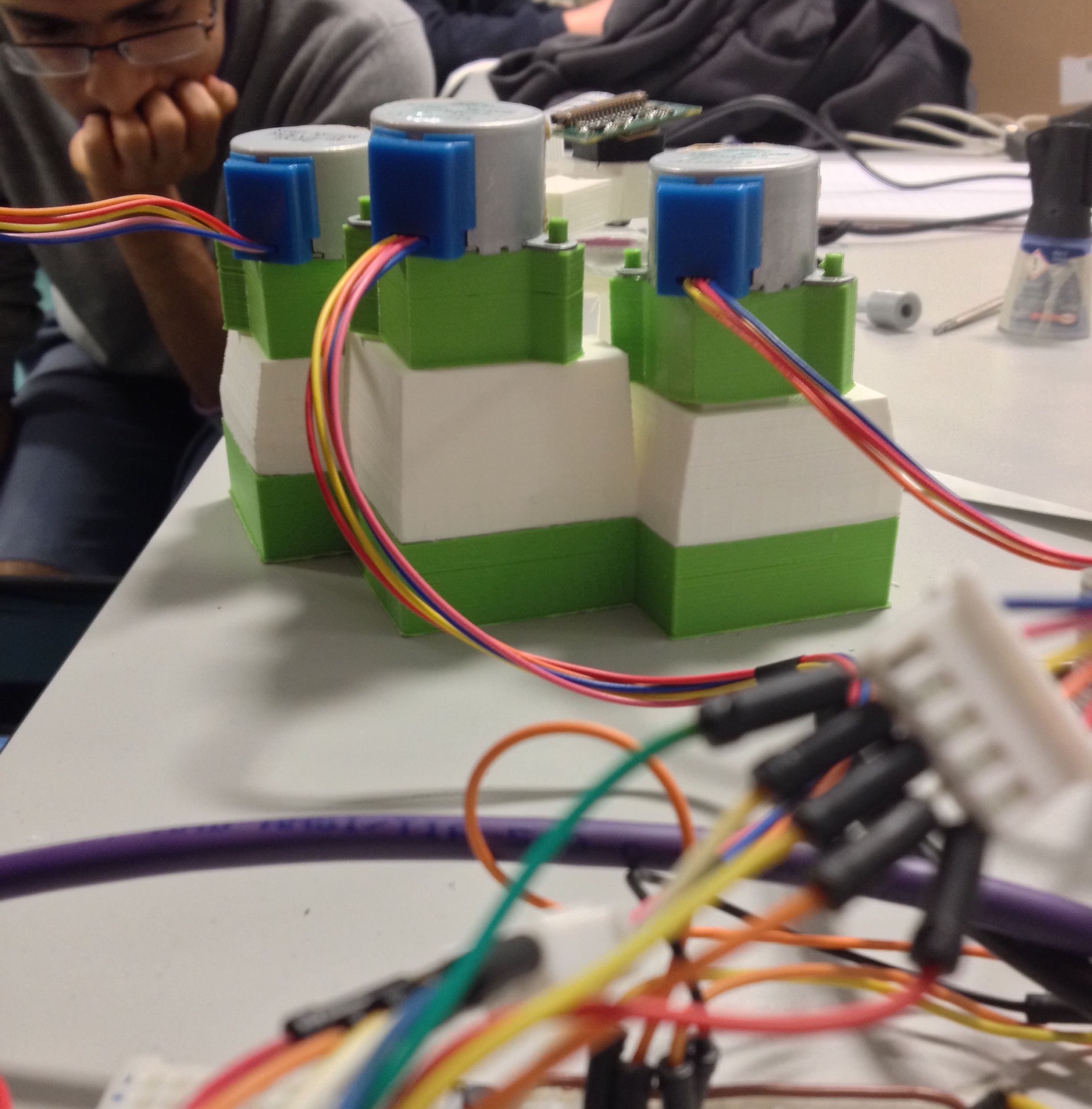 The flexure mechanism allows the stage to move horizontally very smoothly, and all care was taken to provide just as smooth vertical movement. Using screws to control the mechanics provides an extra degree of fine-control. In addition, the microscope can be motorized for complete remote operation (again, through the WebShell). We used cheap, low-power (operating at 5V) stepper motors, which are still highly accurate: they are geared to 513 steps per revolution, which translates into approx. 1.0μm movement of the sample per step along the x- and y-axes. For the detailed analysis, see the document below.
Stage Drift
![]() In order to perform time-lapse imaging, the digital microscope must be left capturing images for long periods of time. However, most microscope stages exhibit a drift, which causes the sample to move during the experiment. OpenScope is not an exception, especially given the fact that the stage is made of plastic. In order to characterise our prototype brightfield microscope, an experiment was set-up to record the movement of points (fiducial marks) on a slide over a period of roughly 16 hours. The detailed experimental findings are available in the PDF below. In spite of the drift, OpenScope is still suitable for time-lapse imaging if used in conjunction with software which is capable of point tracking and drift correction. This involves the use of motors to compensate for drift, and is a strategy used by many commercial microscopes. However, this has not yet been implemented into OpenScope.
In order to perform time-lapse imaging, the digital microscope must be left capturing images for long periods of time. However, most microscope stages exhibit a drift, which causes the sample to move during the experiment. OpenScope is not an exception, especially given the fact that the stage is made of plastic. In order to characterise our prototype brightfield microscope, an experiment was set-up to record the movement of points (fiducial marks) on a slide over a period of roughly 16 hours. The detailed experimental findings are available in the PDF below. In spite of the drift, OpenScope is still suitable for time-lapse imaging if used in conjunction with software which is capable of point tracking and drift correction. This involves the use of motors to compensate for drift, and is a strategy used by many commercial microscopes. However, this has not yet been implemented into OpenScope.
Strength
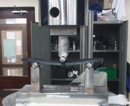 Three point bending tests were performed to confirm the strength of the OpenScope stage. The material used to print it - PLA - turns out to be both 4 times stronger and and 13 times stiffer than the alternative material, ABS. We also explored how different orientations of the object during 3D-printing affects its strength, and took this into account when putting together the OpenScope print files. Moreover, it was confirmed that the plastic is not subject to plastic deformation due to the weight-loads that the OpenScope stage will typically have to bear. In short: you can put OpenScope in your backpack and not worry about it getting broken (we tried this, too). The detailed report from the strength testing experiments can be found below.
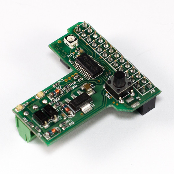
Electronics
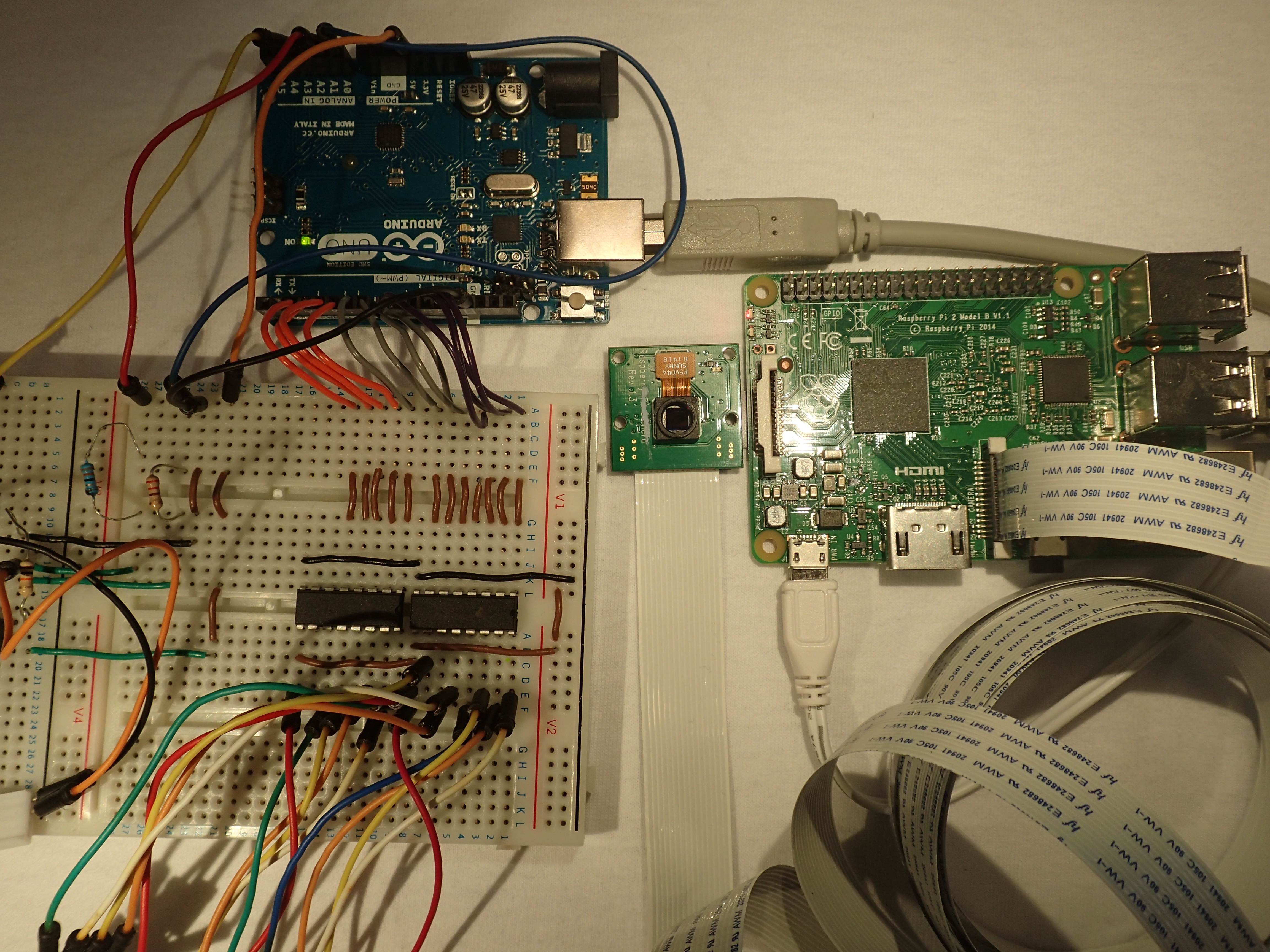
The OpenScope is a digital microscope based on open-source elctronics. Raspberry Pi provides the processing power, required to run the NOOBSCOPE software package, that we created. It enables your OpenScope to stream real-time picture over the WebShell... and much more (Read about this in the Software section). The Raspberry Pi Camera Module is used to capture the high-resolution images. An Arduino powers up the LEDs and motors and is directly controlled via the Pi.
Size & Weight
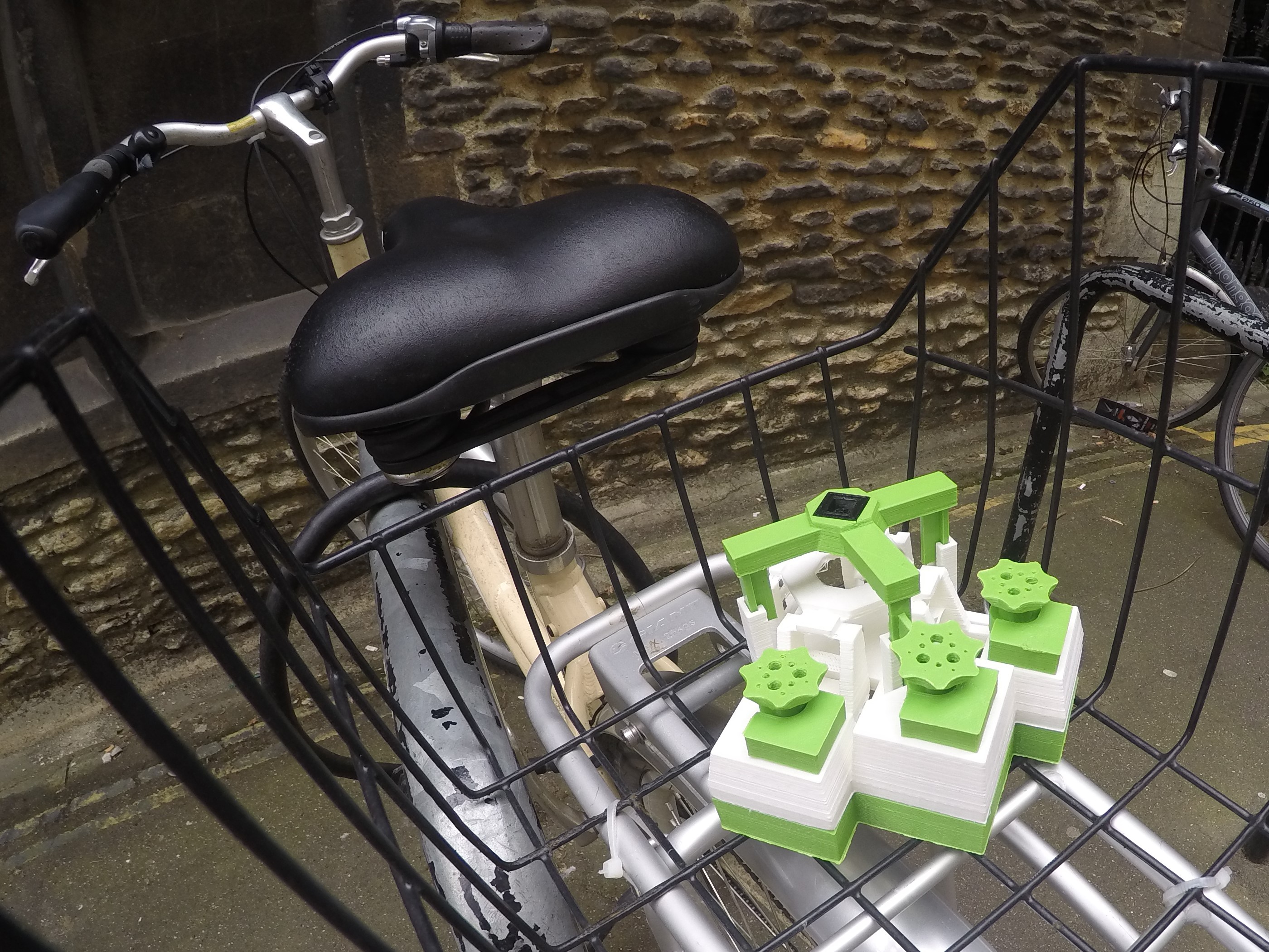 The plastic stage of OpenScope weights just over 100g, and the height of the whole assembly is just over 6cm in height. Together with all of the accompanying electronics, it is easily transportable in a 13x13x13 cm box. A 3m ribbon cable is used to connect the camera to the Raspberry Pi, which gives extra flexibility of movement. However, in order to reduce cable management requirements this can be shortened. In our set-up, the Arduino and Raspberry Pi are not housed in the chassis of the microscope and are stand-alone.
Cleaning
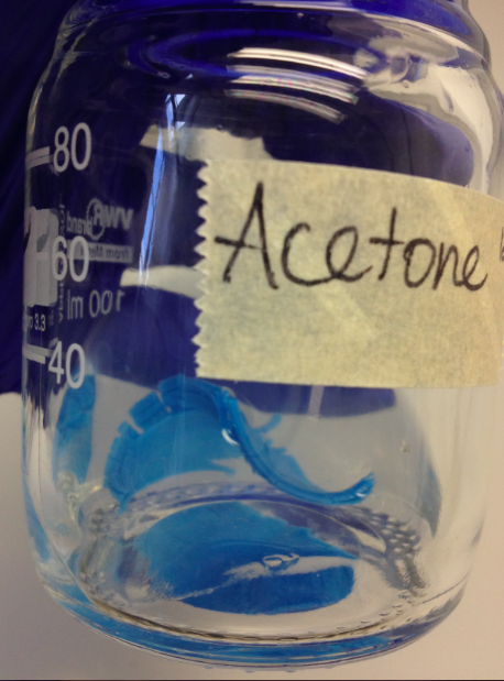 We are aware that an item placed into the sterile environment of an incubator can cause contamination to any living samples. In order to use OpenScope in such a scenario, there must be an effective and non-damaging way to sterilise and clean it. This can be achieved by spraying with isopropanol before using. Isopropanol (propan-2-ol) is safe for the PLA and the electronics. Never attempt to use methanol (this will make the PLA soft) or acetone (this will dissolve the plastic).
Power
 Considering all of the electronics required to run OpenScope, it consumes 10 times less power than just the arc lamp of a typical lab-bench fluorescence microscope. OpenScope can run on battery power for up to 12 hours depending on use. This time was estimated on the basis of a power consumption analysis, as described in the PDF below. To power OpenScope using batteries you will need the MoPi power module for Raspberry Pi and two 9V batteries. We recommend replacing the single 9V cell for a series of 6x1.5 AA batteries for best performance. For this purpose, you can 3D print this battery holder.
The ability of the OpenScope to run on battery power makes it particularly useful for imaging in the field or in incubators, without the need for a standard power supply.