Team:USTC-Software/Results

Demo
Now we will use a specific example to demonstrate functions of BioBless.
- You can input a truth table where "1"represents the existence of the substance and "0" represents the opposite.
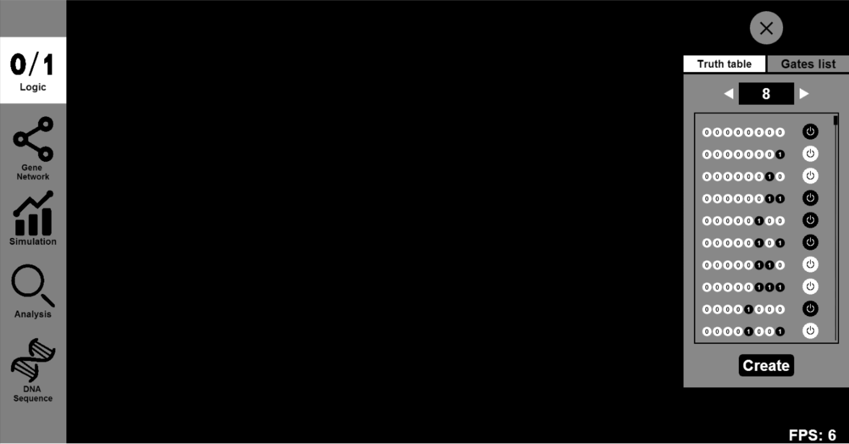
- Our software will provide several possible gene circuits for your truth table. You can drag one of these gene circuits on our canvas.
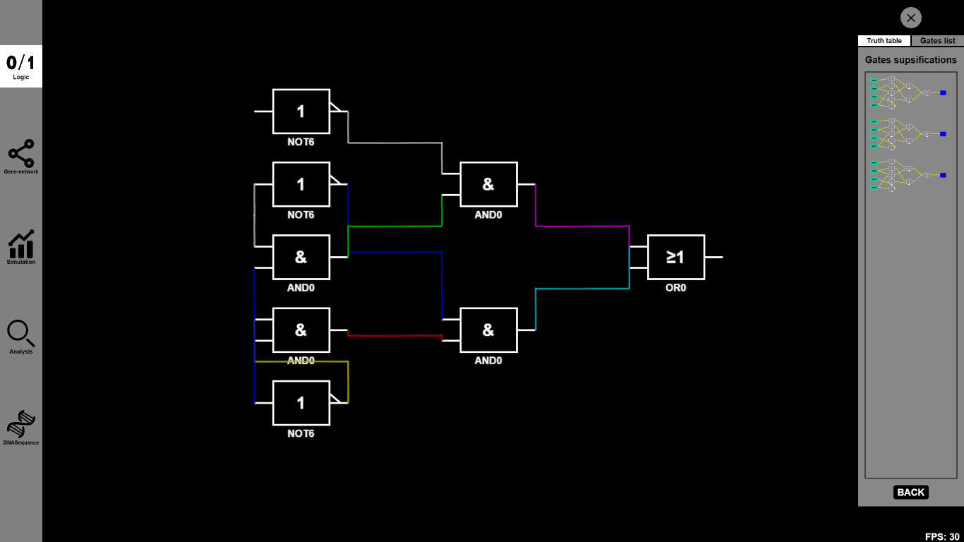
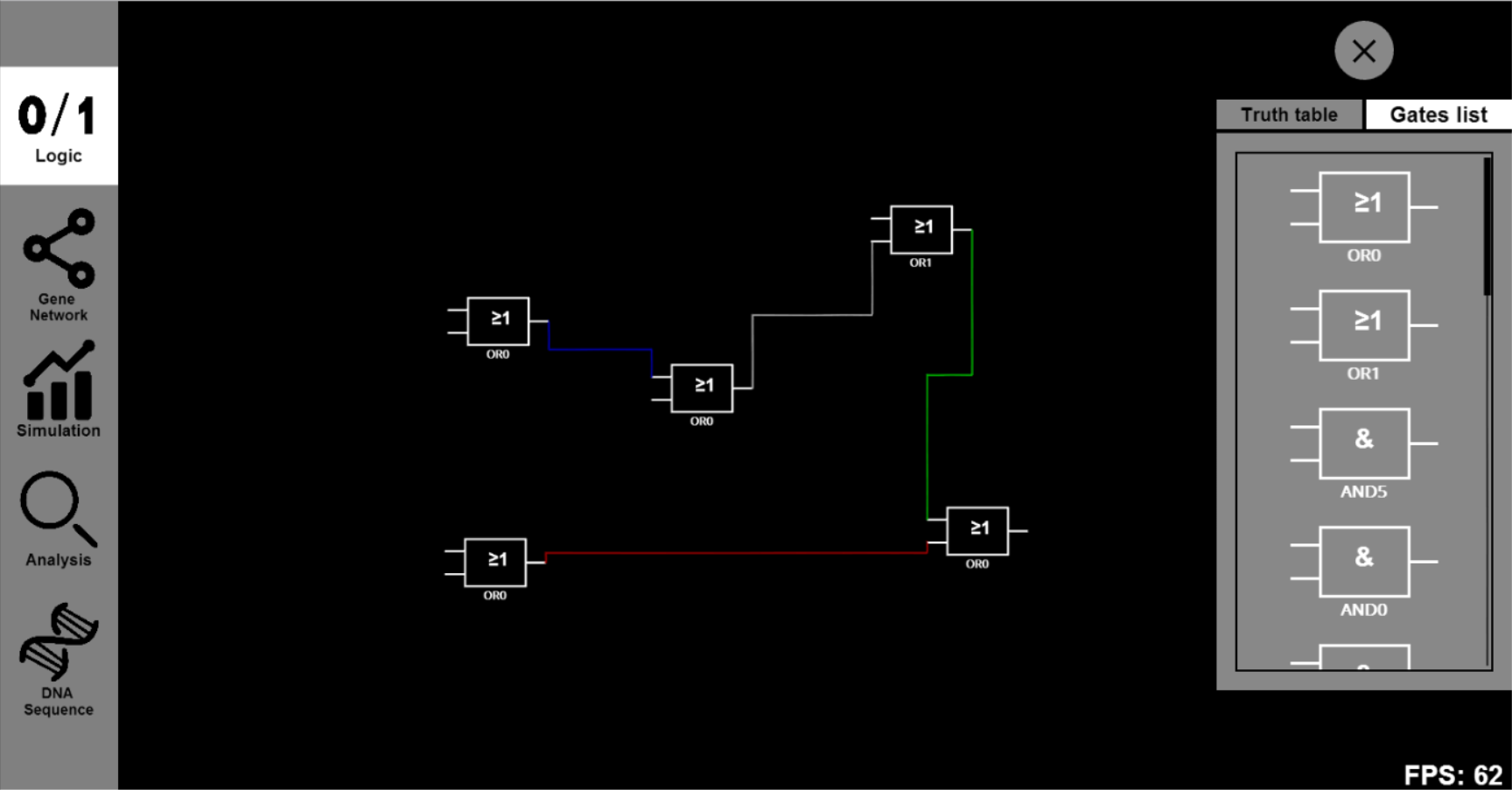
- Now you can either drag some other Boolean gates to the canvas or choose some specific Biobricks to substitute the abstract Biobricks in the designed gene circuit. For example, you can drag several OR0 and OR1 to connect them together.
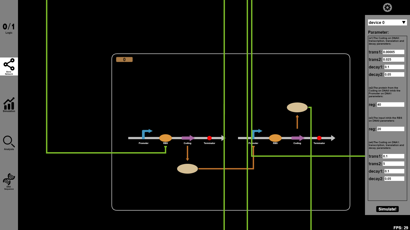
- Click the "Gene Network" button and input parameters you want to change. For example, you can set the reaction parameter of transcription (trans1), translation (trans2), decay1 and decay2 rates as 0.00005, 0.025, 0.1 and 0.05 respectively. Click the icons on our canvas and you will go into a dialog box to choose Biobricks.
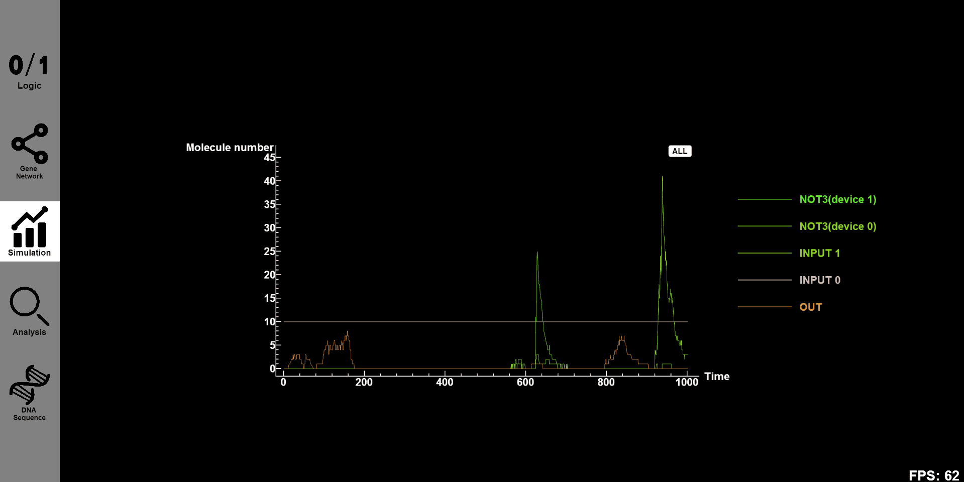
- Click the "Simulation" button and you will see the concentration-time figure of every substance in designed gene circuit. Click on "all" and all figures will be shown on our canvas. Click "OUT"and you will see the concentration-time figure of this substance individual.

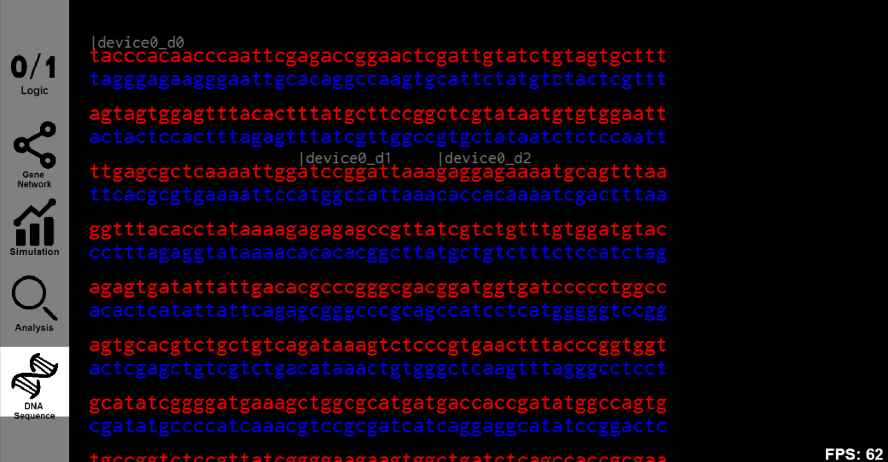
- The "DNA Sequence" button will provide information of the DNA sequence and you will see the sequences of designed gene circuit.
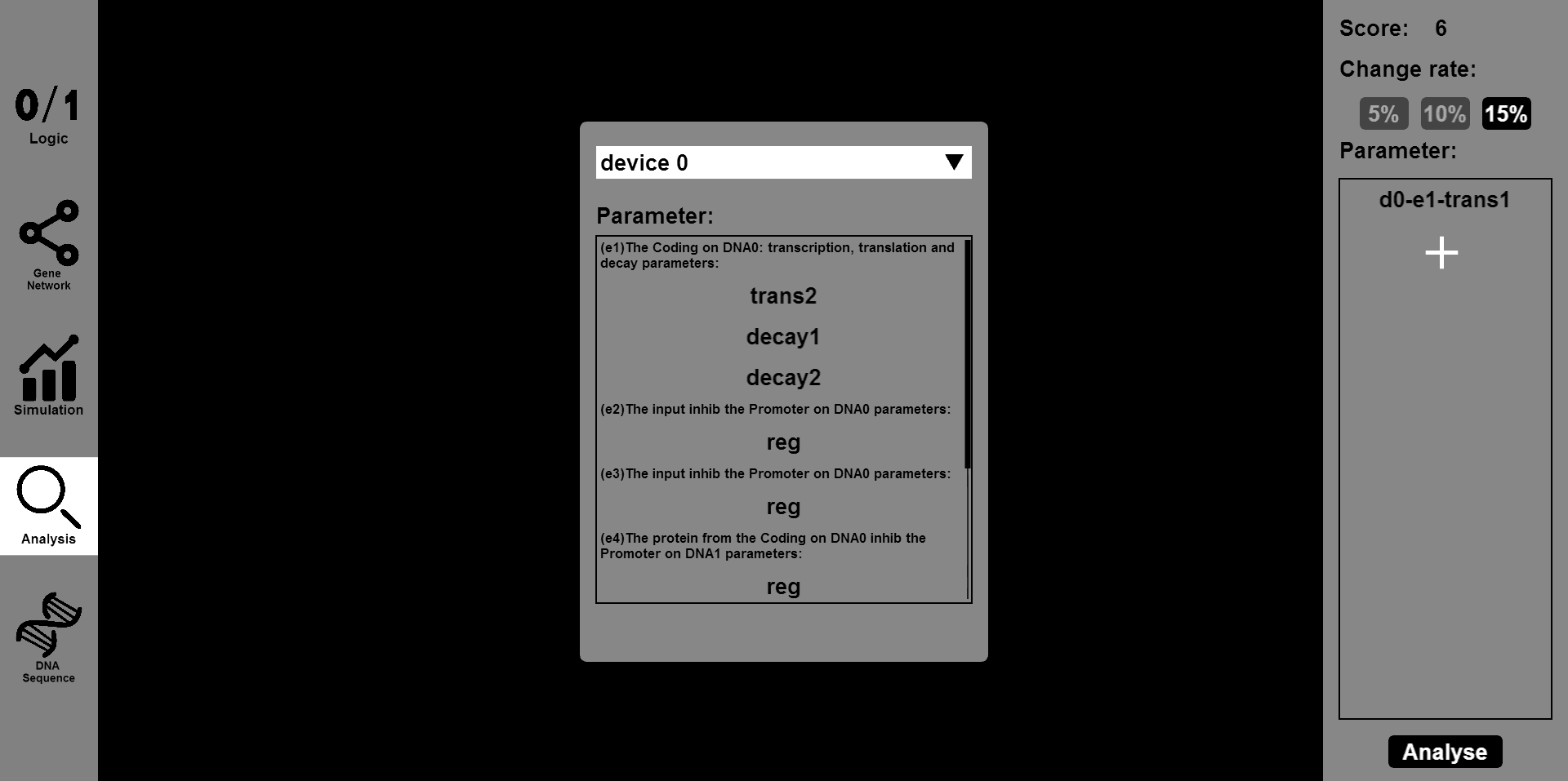
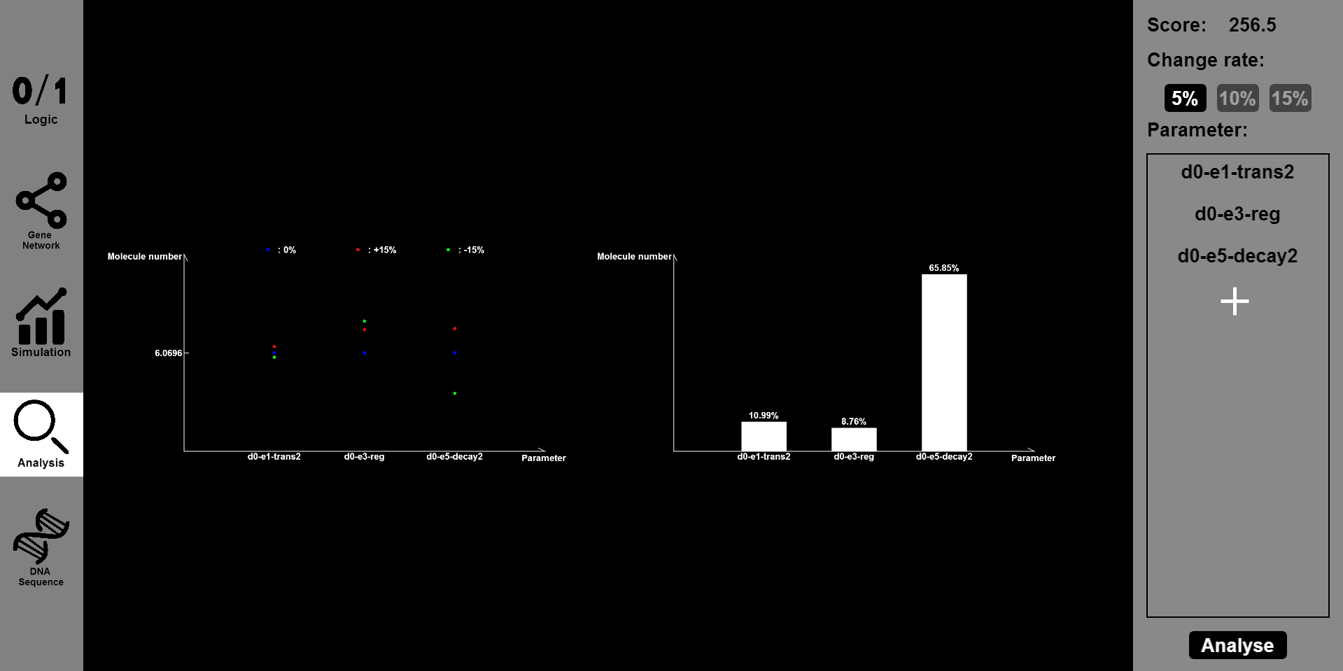
Click the "Analysis" button, then input the parameter you want to change and the range of change, such as 5% or 15%. Then you will see the results of stability and robustness.
Future Work
- Noting that the number of prototype substances for inputs of our gene circuit have been limited, hence the functionality of designed gene circuits are strongly weakened. One of our future work is to design novel gene circuit where the inputs and outputs are arbitrary given. Theoretically, if we build up the bridge between an arbitrary input (denoted by A) and several certain functional protein (denoted by B), for example, biologist can design a specific gene circuit like a combination of A-targeted promoter with gene sequence of B in advance to achieve that the concentration of A will be commensurate with that of B, thus designing pathways between arbitrary input and output substances.
- Externalization: Since we aim at providing synthetic biologists a user-friendly and helpful tool to design gene circuit, concrete biology entities should not be omitted. Abstract inputs and outputs will be substituted by specified substances chosen scrupulously in case cross talk or other mutual reactions undermine the functionality of designed gates. Although the choice of appropriate promoters, RBS, transcription factors can be intractable, a library of prototype substance for inputs and outputs together with experiment-based sequence design will enable us to build more complex gene circuits. Unrealizable complexity is far from the pursuit of synthetic biologists, based on wet-lab experiments, reasonable rules will be introduced into our software to preclude those gates heavily taxing engineering bacteria.
- Library Enrichment: More effective and functional logic elements and sequences, even some Boolean gates with memory are expected to be added into our library. The trend of synthetic biologists designing more biobricks with logic functions and submitting them to Standard Biobrick Registry requires more sophisticated and elaborated parameters to measure the usability of designed gene circuits and biobricks. A user administration system or community may be helpful to setting standards for biobrick measurement and evaluation.
- Accuracy: Improving the accuracy and predictability of our simulation is another critical work undergoing. Although stochastic simulation can shed great insight on the performance of designed gene circuits, more work can be done in the future. To analyze designed circuits more comprehensively and thoroughly, several different simulation methods will accompany stochastic simulation in our software.
- Platform: Our software is developed to help biologists to construct functional gene circuits in lab. The complex nature of a biological system calls for collaboration between different tools. Although many software teams before have developed many computer-aided design tools, a platform for different tools to work together has not been well developed. In order to best design functional gene circuit, our software hopes to provide a platform where function-related tools can be integrated to work together.
Validation
General thesis
A convincing validation of BioBLESS includes two aspects. One is whether our simulation results correspond to the inputted truth table and the other one is whether the simulation results of designed gene circuits satisfy the experimental results which have been realized in lab. Furthermore, there are two factors that matter a lot in analysis part of BioBLESS, ACCURACY and APPLICABILITY. Accuracy describes how well our algorithms can simulate the realistic experimental results and applicability determines whether designed gene circuits from truth table can be applied in real experiments.
PART 1
The first part below is the validation of BioBLESS algorithms. Consider the performance of Boolean gates. The following simulation results will illustrate the good behavior of Boolean gates.
Name: NOT
Results:
 Input=[0] |
 Input=[1] |
Name: AND
Results:
 Input=[00] |
 Input=[10] |
 Input=[11] |
 Input=[01] |
Name: OR
Results:
 Input=[00] |
 Input=[10] |
 Input=[01] |
 Input=[11] |
All detailed parameters about our logic gates can be seen on GitHub
PART 2
Then we consider whether the performance of Boolean gate cascades is good enough. We will examine a biology example and first extract the modelling part of it. Later we will discuss whether our simulation results correspond to experiments.
Truth table
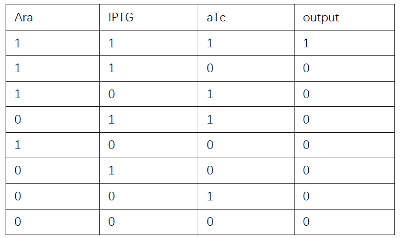
Then we are going to discuss whether our simulation corresponds to wet-lab experiments.
Background
Each AND gate integrates two promoter inputs and controls one promoter output. This allows the gates to be layered by having the output promoter of an upstream circuit serve as an input promoter for a downstream circuit. Each gate consists of a transcription factor that requires a second chaperone protein to activate the output promoter. These gates are connected in different permutations to form programs, the largest of which is a 4-input AND gate consisting of 3 circuits that integrate 4 inducible systems, thus requiring 11 regulatory proteins. Measuring the performance of individual gates is sufficient to capture the behavior of the complete program.
Method
"Strains, plasmids and growth media. E. coli DH10B was used for all the experiments and growninLuria¨CBertani (LB) medium (Miller,BDBiosciences). Kanamycin (20 mg/ml), ampicillin (100 mg/ml) and chloramphenicol (34 mg/ml) were added as appropriate. Four inducers were obtained from Sigma Aldrich: Ara (Arabinose), IPTG (isopropyl b-D-1-thiogalactopyranoside), 3OC6 (N-(bketocaproyl)-L-homoserine lactone) and aTc (anhydrotetracycline). All the newly constructed plasmids were made by the one-step isothermal DNA assembly method as described previously.
"Part mutagenesis. Promoter regions were modified by saturation mutagenesis. To construct the promoter libraries, the bases were randomized by using oligonucleotides (Integrated DNA Technologies) as shown in Supplementary Fig. 3. After PCR reactions, the blunt ends were ligated with T4 DNA ligase (New England BioLabs) to give the mixture of the modified plasmids. To obtain sicA variants, error-prone PCR was performed. Random mutations were introduced by PCR reactions with 13PCR buffer supplemented with 7mM MgCl2, 0.3mM MnCl2,
0.2mM dATP, 0.2mM dGTP, 1mM dCTP, 1mM dTTP and 0.05U Taq DNA polymerase (Invitrogen). The detailed methods including library screening are described in Supplementary Methods.
Flow Cytometer. E. coli was grown overnight in LB medium at 37 Celsius degree and then transferred to fresh LB medium in 96-well plates (USA Scientific). Each culture (0.6 ml) was induced at a D600 of 0.5 (unless otherwise specified) with inducers of different concentrations as indicated, and flow cytometer data were obtained using an LSRII flow cytometer (BD Biosciences). All the data were gated by forward and side scatter, and each data consists of at least 10,000 cells. The arithmetic mean fluorescence was calculated with FlowJo (TreeStar Inc.), and the averages of means were obtained from three replicates performed on different days."
Reference: Moon, T.S., Lou, C., Tamsir, A., Stanton, B.C. & Voigt, C.A. Genetic programs constructed from layered logic gates in single cells. Nature 491, 249¨C253 (2012).
The picture given in the paper:
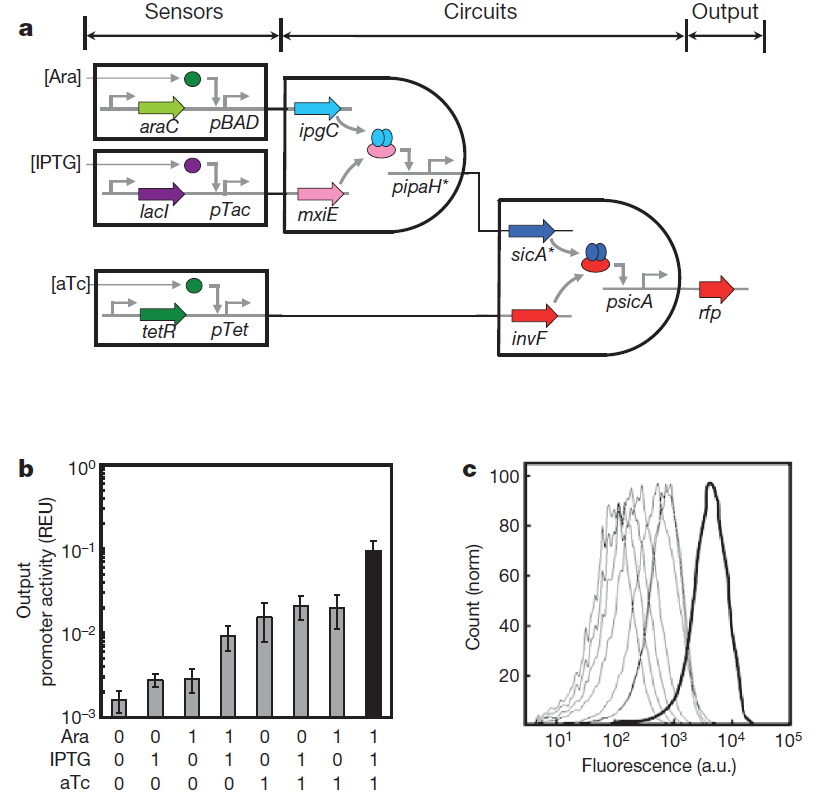
Fig. 0 Genetic circuits formed by layering AND gates. a, 3-input AND gate. This system consists of three sensors, an integrated circuit and a reporter gene. b, The fluorescence measured from cells containing the 3-input AND gate. The three inducers used for the on (1) input are Ara (5mM), IPTG (0.1mM) and aTc (10 ng/ml). Data are means and s.d. for three replicates performed on different days. c, Raw cytometry data for all sets of input states. The thick line is for the [111] set of inducers.
Our results
 |
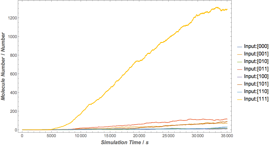 |
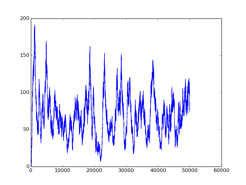
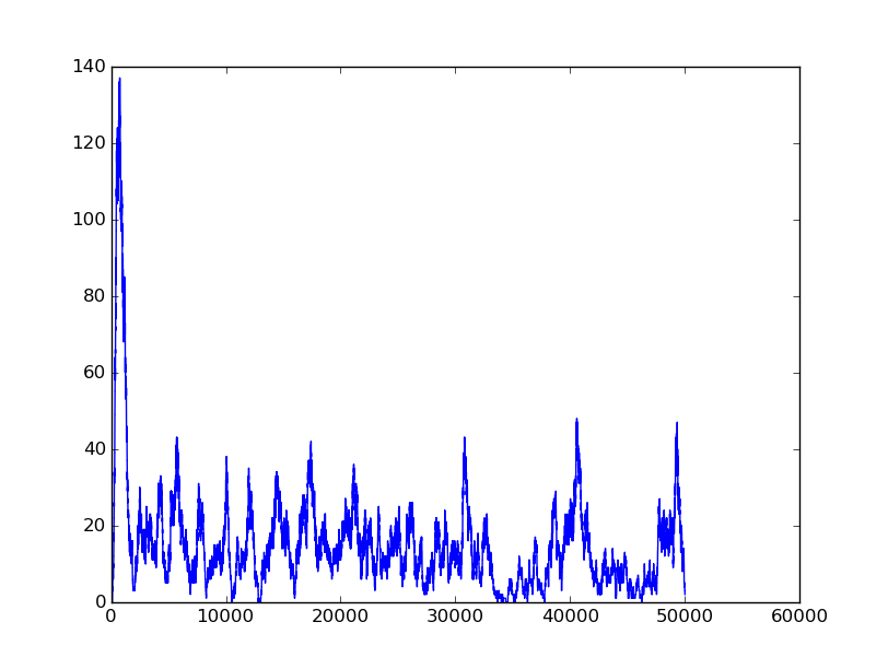
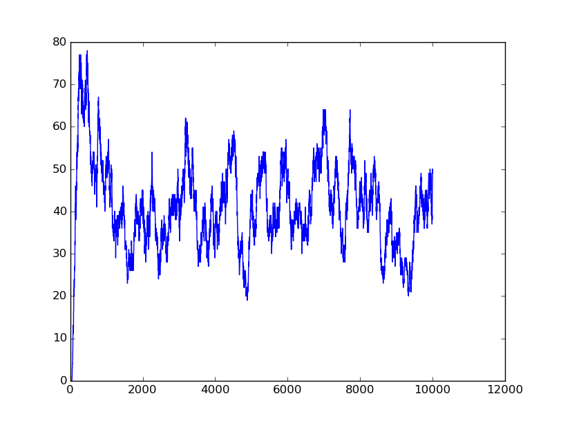
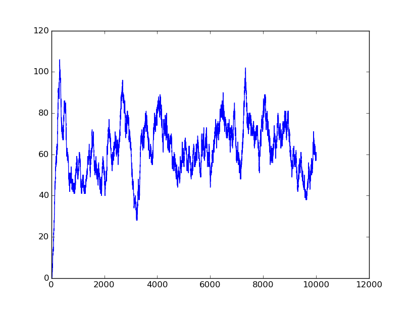
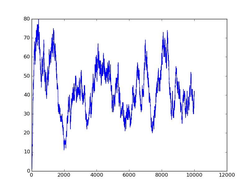
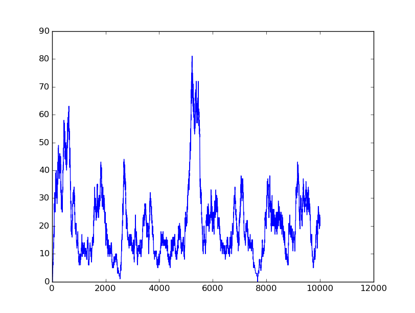
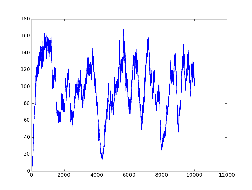
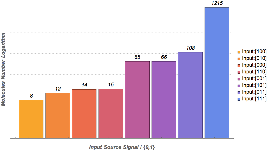
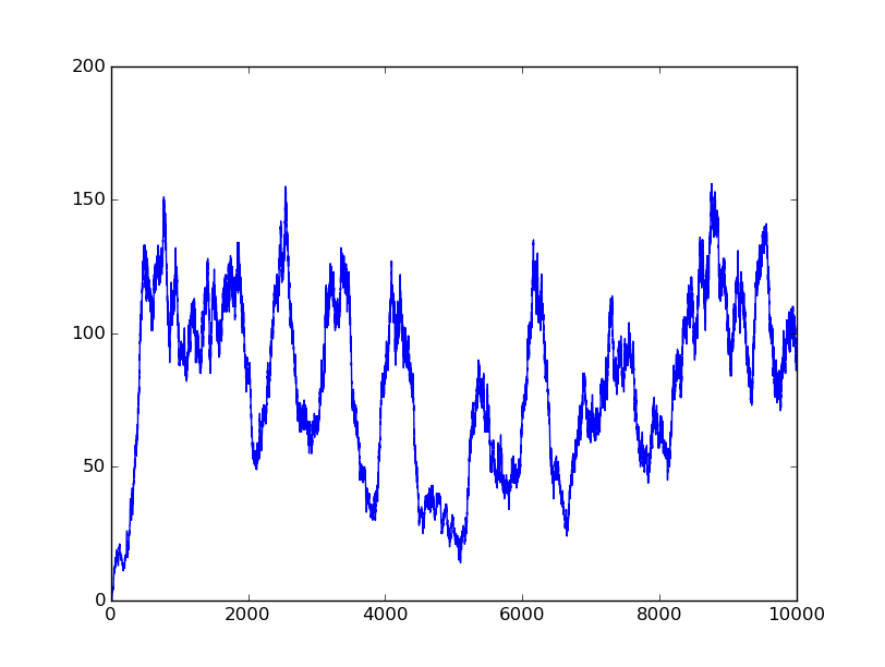
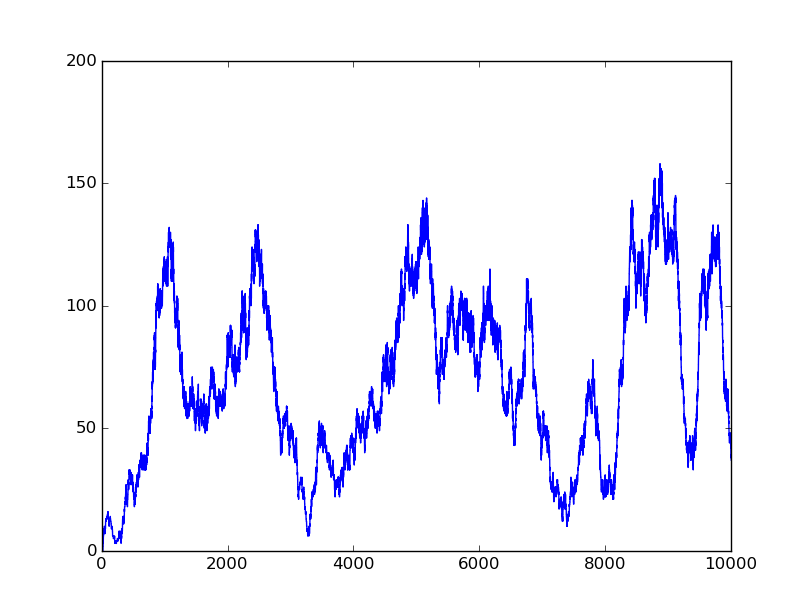
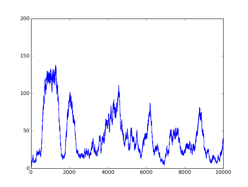
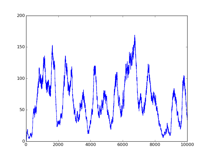
Based on the logical relationship between the output and inputs, we summarize it into a truth table and BioBLESS will design a gene circuit. Stochastic simulation with different parameters, namely the combination of 0/1 of inputs, will be carried out to give predicted performance of different input states. The peak value of concentration-time figures based on different input states will be arrayed in an ascending order coincidently similar to the order shown in Fig. 0(b). When all three inputs are present, the output of the designed gene circuit rises all above other situations. Sets with aTc present but not all present shares similar outputs. These outputs are evidently higher than those sets without aTc whose outputs stay in low levels.
Further analysis
There is no clock that synchronizes the progression of the signal between gates. There are delays at each layer which can lead to transient errors in the output, known as faults. A fault may occur when a signal is divided and one branch skips a layer (for example, in Fig. 0(a) the pTet input signal skips the first layer). Because the on signal reaches the next layer faster than the other, the gate at the second layer will transiently respond to the wrong state of input signals. One characteristic of the designed three-input AND gate is that the existence of aTc can evidently increase the output. A comparison between set [110] and [001] will shed light on this point. The transmission of aTc signal doesn't have as much layers as IPTG or Ara. Our software presets same parameters for same gates and biologists can employ their experience to fine tune parameters to fit in different situations. The result shows the transient errors.
Especially when we switch the state [111] to [000], a well-behaving gene circuit should ensure that the output will switch off quickly. Thus one protocol of parameter selection is that the decay rate of protein or small RNA, especially those functioning as a medium, should be higher than corresponding transcription and translation rates.
PART 3
In this part, we will design a more complicated logic circuits and show that our simulation fits the original truth table well.
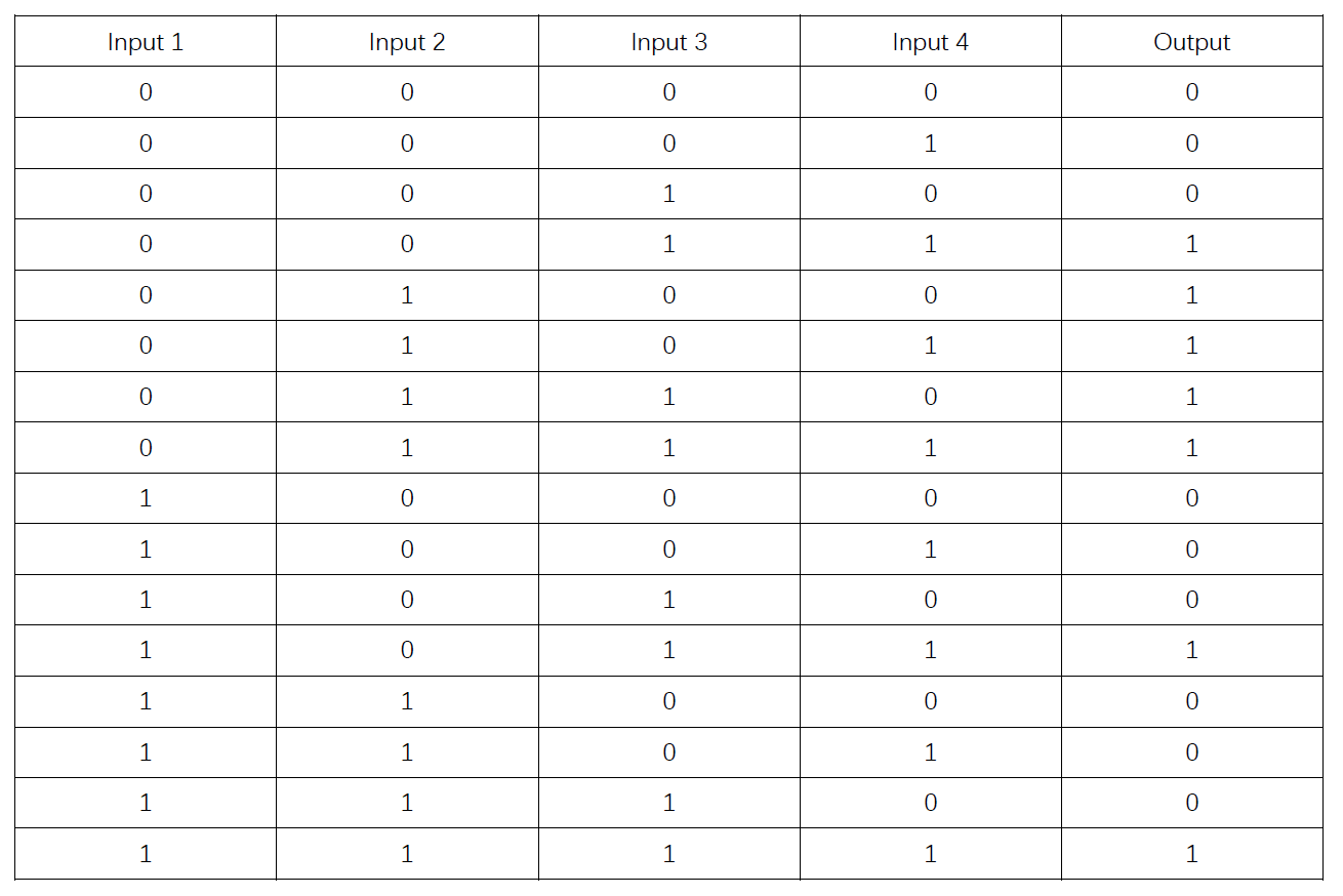
Truth table
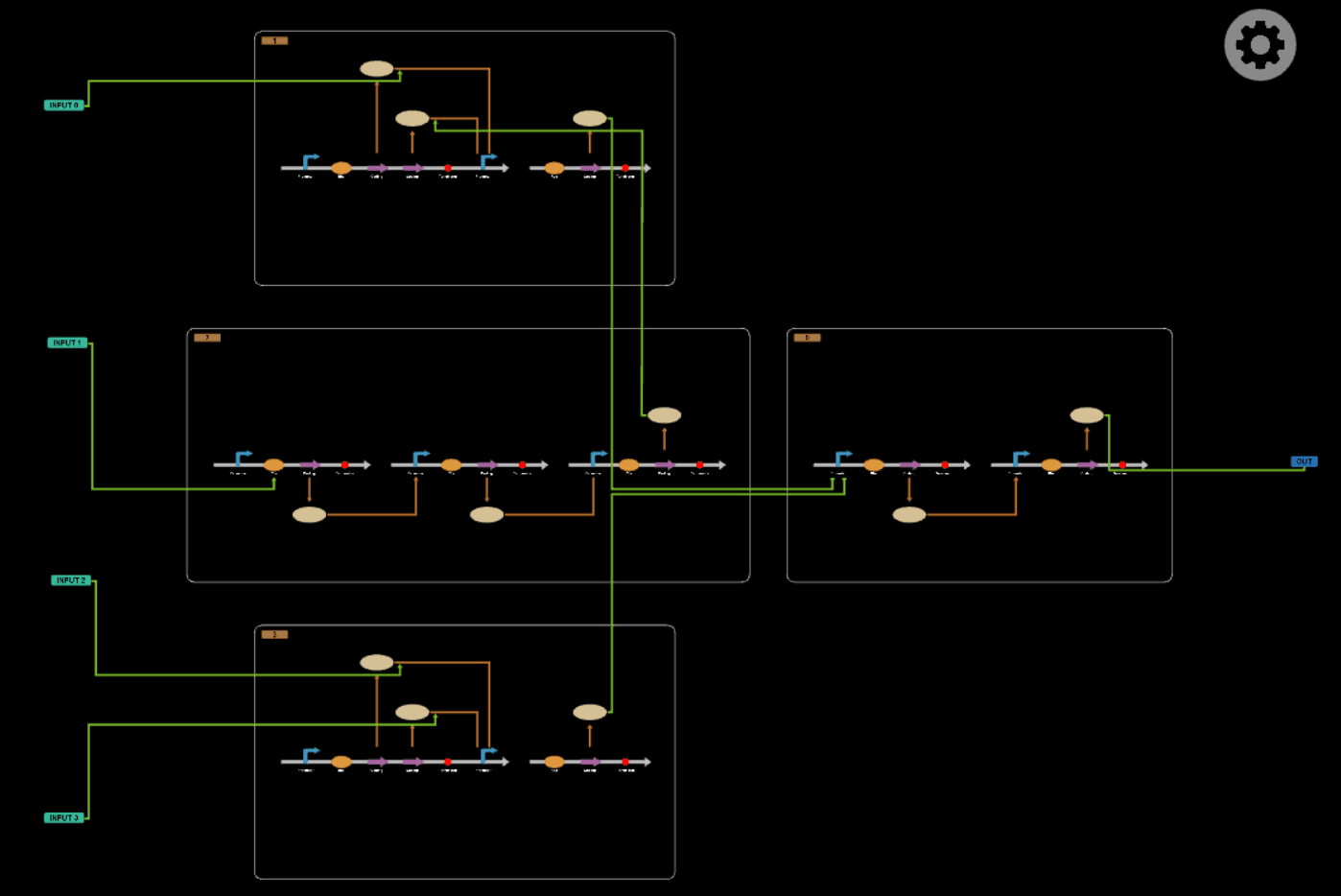
Logic circuits generated by BioBLESS
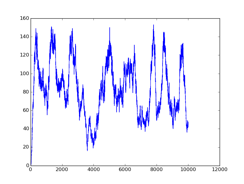
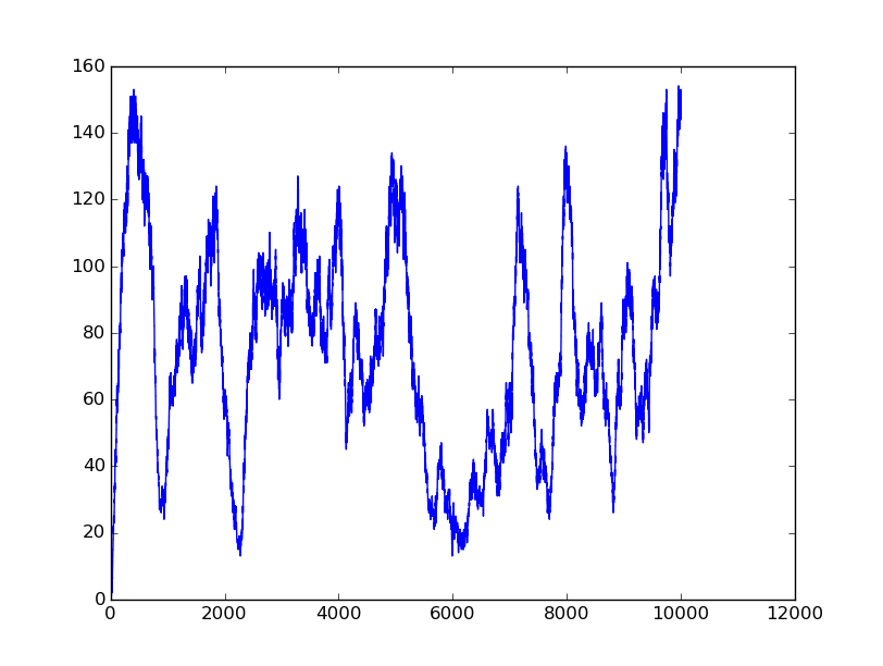
Simulation results
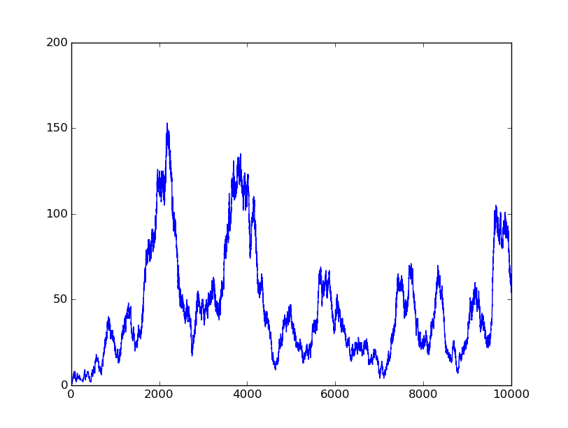 0000 |
 0010 |
 0101 |
 0110 |
 1001 |
 1011 |
