Difference between revisions of "Team:Chalmers-Gothenburg/ProjectResults"
| Line 4: | Line 4: | ||
<p>• SS TPK2 shows reduced growth rate after OD-measurement but no change in viability compared to wild type.</p> | <p>• SS TPK2 shows reduced growth rate after OD-measurement but no change in viability compared to wild type.</p> | ||
<p>• Fluorescent measurements show that connection of pTEF1 to pSUC2 maintains the ATP repression mechanism of pSUC2, while achieving higher expression at low ATP levels.</p> | <p>• Fluorescent measurements show that connection of pTEF1 to pSUC2 maintains the ATP repression mechanism of pSUC2, while achieving higher expression at low ATP levels.</p> | ||
| − | <p>• Successfully constructed and integrated the system to detect the P-factor from S.pombe into CEN.PK2.</p> | + | <p>• Successfully constructed and integrated the system to detect the P-factor from <i>S.pombe</i> into CEN.PK2.</p> |
<p>• Fluorescent cells in the Detection System</p> | <p>• Fluorescent cells in the Detection System</p> | ||
<p>• Amplified all parts of the DNA repair system, but obtained vector-only clones after Gibson and transformation into E.coli</p> | <p>• Amplified all parts of the DNA repair system, but obtained vector-only clones after Gibson and transformation into E.coli</p> | ||
<h3>Detection system</h3> | <h3>Detection system</h3> | ||
| − | <p>The system without the amplification through dCAS9-VP64 (construct 4) was successfully assembled and integrated into S.cerevisiae CEN.PK2. The genomic integration was verified with colony PCR and sequencing. The detection system was initially intended to be integrated into IMFD-70, but as several transformations failed the strain was changed to CEN.PK2 instead.</p> | + | <p>The system without the amplification through dCAS9-VP64 (construct 4) was successfully assembled and integrated into <i>S.cerevisiae</i> CEN.PK2. The genomic integration was verified with colony PCR and sequencing. The detection system was initially intended to be integrated into IMFD-70, but as several transformations failed the strain was changed to CEN.PK2 instead.</p> |
<p>The construction of the application systems (construct 2 and 3) was unsuccessful. The fragments of the constructs was individually amplified with PCR, see figure 1, but only clones with empty vectors were obtained after Gibson assembly and transformation into E.coli.</p> | <p>The construction of the application systems (construct 2 and 3) was unsuccessful. The fragments of the constructs was individually amplified with PCR, see figure 1, but only clones with empty vectors were obtained after Gibson assembly and transformation into E.coli.</p> | ||
| Line 57: | Line 57: | ||
<h3>Safety switch</h3> | <h3>Safety switch</h3> | ||
| − | <p>All three variants of the safety switch (pTEF1-pSUC2-TPK2, pTEF1-pSUC2-<i>mRFP</i> and pSUC2-<i>mRFP</i>) was successfully integrated into the genome of S.cerevisiae CEN.PK2 and verified by colony PCR and sequencing.</p> | + | <p>All three variants of the safety switch (pTEF1-pSUC2-TPK2, pTEF1-pSUC2-<i>mRFP</i> and pSUC2-<i>mRFP</i>) was successfully integrated into the genome of <i>S.cerevisiae</i> CEN.PK2 and verified by colony PCR and sequencing.</p> |
<h4>SS TPK2</h4> | <h4>SS TPK2</h4> | ||
| − | <p>The results for continuous OD-measurement of the wild type S.cerevisiae CEN.PK2 (WT) and CEN.PK2 with integrated safety switch (SS) in YPD are shown in figure 8.</p> | + | <p>The results for continuous OD-measurement of the wild type <i>S.cerevisiae</i> CEN.PK2 (WT) and CEN.PK2 with integrated safety switch (SS) in YPD are shown in figure 8.</p> |
<p>[[File:ChalmersGothenburgSsTpk2.jpg|500px]] | <p>[[File:ChalmersGothenburgSsTpk2.jpg|500px]] | ||
| Line 73: | Line 73: | ||
<h4>SS mRFP</h4> | <h4>SS mRFP</h4> | ||
| − | <p>Expression of <i>mRFP</i> (monomeric Red Fluorescent Protein) was used to analyze expression levels of the safety switch. To evaluate the effect of connecting pTEF1 to pSUC2, two different versions were made: pTEF1-pSUC2-<i>mRFP</i> and pSUC2-<i>mRFP</i>. Both constructs were integrated into the genome of S.cerevisiae CEN.PK2. The fluorescence of the clone with integrated pTEF1-pSUC2-<i>mRFP</i> (TEFSUC) and the clone with pSUC2-<i>mRFP</i> (SUC) was compared with wild type CEN.PK2 (WT).</p> | + | <p>Expression of <i>mRFP</i> (monomeric Red Fluorescent Protein) was used to analyze expression levels of the safety switch. To evaluate the effect of connecting pTEF1 to pSUC2, two different versions were made: pTEF1-pSUC2-<i>mRFP</i> and pSUC2-<i>mRFP</i>. Both constructs were integrated into the genome of <i>S.cerevisiae</i> CEN.PK2. The fluorescence of the clone with integrated pTEF1-pSUC2-<i>mRFP</i> (TEFSUC) and the clone with pSUC2-<i>mRFP</i> (SUC) was compared with wild type CEN.PK2 (WT).</p> |
<p>The first sample of TEFSUC, SUC and WT was cultivated for 2 hours in YPD. The results from fluorescent microscopy are shown in figure 11-14.</p> | <p>The first sample of TEFSUC, SUC and WT was cultivated for 2 hours in YPD. The results from fluorescent microscopy are shown in figure 11-14.</p> | ||
Latest revision as of 01:46, 19 September 2015


Contents
Overview
• Assembled and integrated two different safety switches, based on TPK2 overexpression or mRFP expression induced at low ATP levels, into CEN.PK2.
• SS TPK2 shows reduced growth rate after OD-measurement but no change in viability compared to wild type.
• Fluorescent measurements show that connection of pTEF1 to pSUC2 maintains the ATP repression mechanism of pSUC2, while achieving higher expression at low ATP levels.
• Successfully constructed and integrated the system to detect the P-factor from S.pombe into CEN.PK2.
• Fluorescent cells in the Detection System
• Amplified all parts of the DNA repair system, but obtained vector-only clones after Gibson and transformation into E.coli
Detection system
The system without the amplification through dCAS9-VP64 (construct 4) was successfully assembled and integrated into S.cerevisiae CEN.PK2. The genomic integration was verified with colony PCR and sequencing. The detection system was initially intended to be integrated into IMFD-70, but as several transformations failed the strain was changed to CEN.PK2 instead.
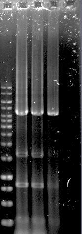
The construction of the application systems (construct 2 and 3) was unsuccessful. The fragments of the constructs was individually amplified with PCR, see figure 1, but only clones with empty vectors were obtained after Gibson assembly and transformation into E.coli.
Construct 1 was successfully assembled and transformed into E.coli, see figure 2, but the construct is not functional without construct 2 and 3. Because of this limitation, no further steps were taken with construct 1.
Figure 1.Well 1: 1kb ladder. Well 2 and 3: unpurified dCas9-Vp64. Well 4: purified dCas9-Vp64. Expected length: 4335 bp.
Construct 1 was successfully assembled and transformed into E.coli, see figure 2, but the construct is not functional without construct 2 and 3. Because of this limitation, no further steps were taken with construct 1.
Figure 2. Construct 1 digested with MfeI. Expected fragments: 214, 2656 and 5926 bp.
Detection test
The fluorescent microscopy pictures from the detection test with CEN.PK2 containing construct 4 (C4) are shown in figure 3-6. Samples were made with different amounts of concentrated P-factor and compared with wild type CEN.PK2 (WT).
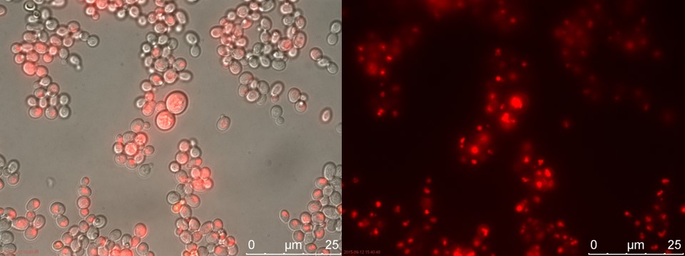
Figure 3. Positive control. Left: overlay channels (bright field, RFP and GFP). Right: RFP channel.
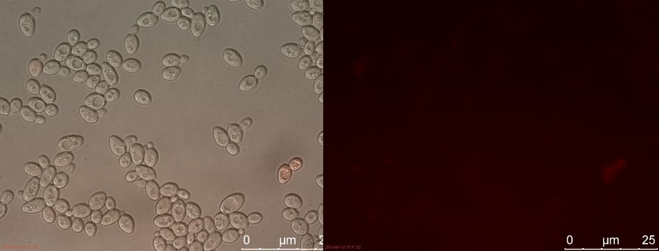
Figure 4. C4 with 230 µl concentrated P-factor. Left: overlay channels (bright field, RFP and GFP). Right: RFP channel.
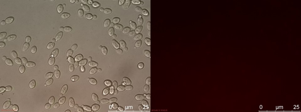
Figure 5. C4 without P-factor. Left: overlay channels (bright field, RFP and GFP). Right: RFP channel.
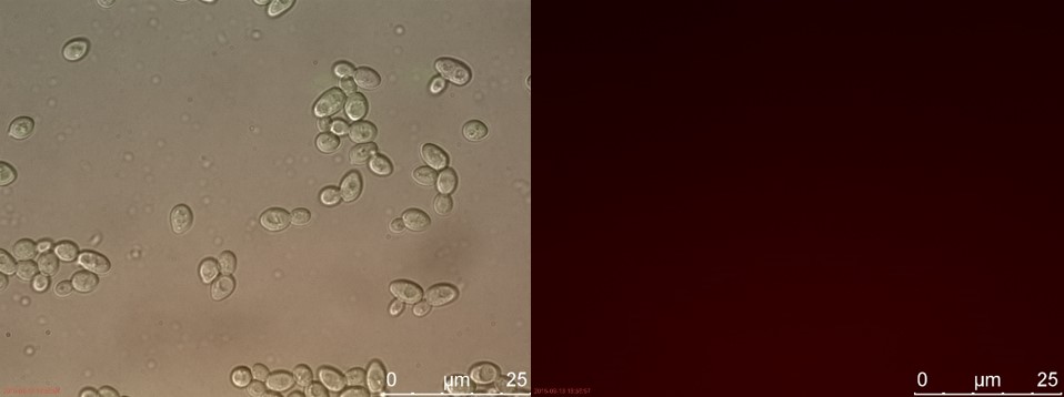
Figure 6. WT with 230 µl concentrated P-factor. Left: overlay channels (bright field, RFP and GFP). Right: RFP channel.
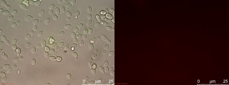
Figure 7. WT without P-factor. Left: overlay channels (bright field, RFP and GFP). Right: RFP channel.
Only the C4 samples containing the highest amount of P-factor showed a few fluorescent cells, which is promising for our concept. The weak signal can be explained by the fact that constructs containing the amplification system through dCas9-vp64 could not be completed. This forces the detection system to rely on the presumably weak promoter pFUS1 to express mRFP. This can result in a weak fluorescent signal when the P-factor is detected.
DNA Repair System
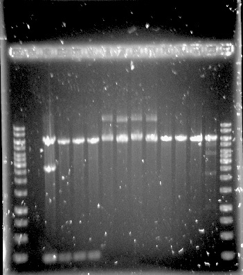
The PUR genes were successfully amplified through PCR, see figure 8, but only clones with empty vectors were obtained after Gibson assembly and transformation into E.coli. One of the problems could have been the size of the constructs, which was around 11-12 kbp, as only chemical transformation into E.coli was used. Although, it is not certain that electroporation would have solved the problem, as the chemical transformation yielded only very few colonies, all of them containing empty vectors.
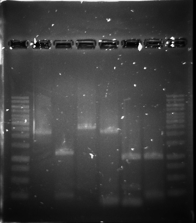
Figure 8. 1kb ladder, RecJ, RecA, RecQ, RecD2, SSB, PprA and 1kb ladder.
We cannot tell if this system will work in the same way in a yeast model as it does in D. radiodurans. We did not have enough time to evaluate optimizations, such as additional enzymes needed, as a lot of time was spend on trial and error in the construction of the current DNA repair system. We laid our focus on the other two systems

Figure 8. 1kb ladder, RecJ, RecA, RecQ, RecD2, SSB, PprA and 1kb ladder.
Safety switch
All three variants of the safety switch (pTEF1-pSUC2-TPK2, pTEF1-pSUC2-mRFP and pSUC2-mRFP) was successfully integrated into the genome of S.cerevisiae CEN.PK2 and verified by colony PCR and sequencing.
SS TPK2
The results for continuous OD-measurement of the wild type S.cerevisiae CEN.PK2 (WT) and CEN.PK2 with integrated safety switch (SS) in YPD are shown in figure 8.
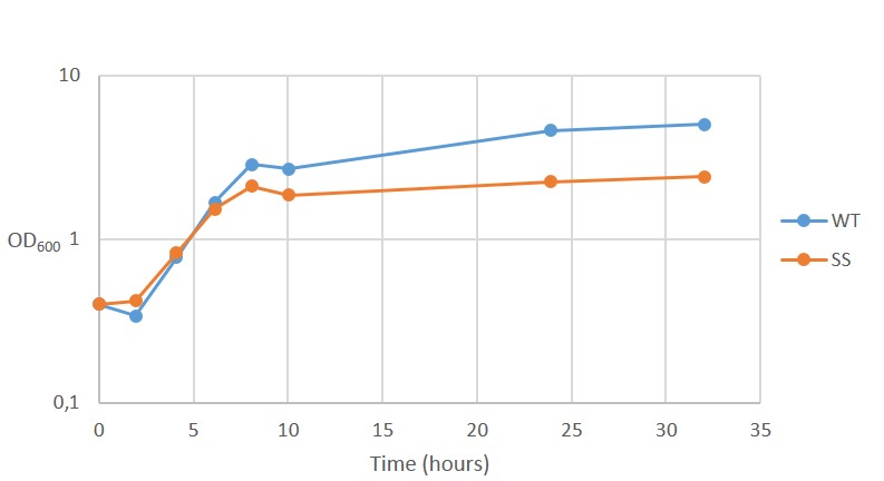
Figure 8. Growth curve of Wild type CEN.PK2 (WT) and recombinant CEN.PK2 with the safety switch (SS).
The measurements indicates that both WT and SS grow initially at the same rate but after ~6 hours, as energy (glucose) levels starts to decline, SS continues to grow at a reduced rate. This is not ideally as the safety switch is supposed to kill the cells, instead of just reduce its growth rate.
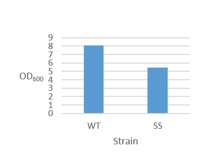
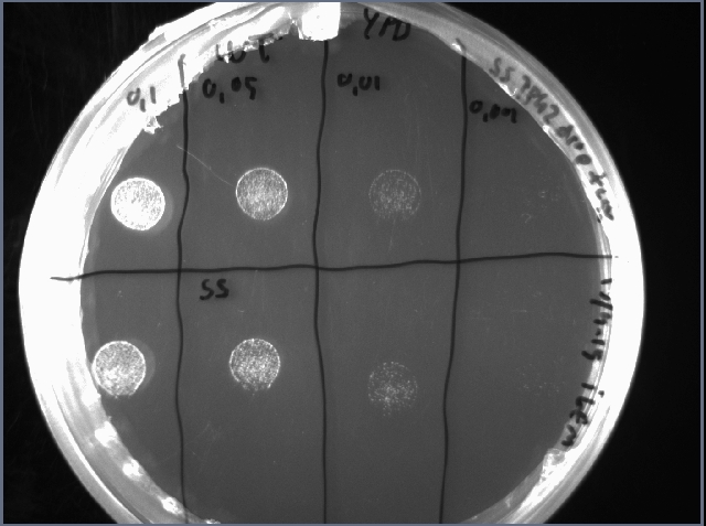
To check if the reduced growth rate was caused by reduced viability of the cells, a drop test was performed after 48 h cultivation in YPD. 10 µL of serially diluted cell suspension was spotted on an YPD plate and incubated overnight. The OD-measurement after 48 hours cultivation is shown in figure 9 and the drop test in figure 10.
Figure 9. OD600 after 48 hours cultivation. Figure 10. Drop test of WT (above) and SS (below). Serially diluted to OD 0.1, 0.05, 0.01 and 0.001
There is no clear difference in viability between WT and SS which indicates that overexpression if TPK2 in this system causes reduced growth rate but no obvious change in viability. A solution for this insufficient safety switch could be to change the TPK2 to a more harmful gene.
SS mRFP
Expression of mRFP (monomeric Red Fluorescent Protein) was used to analyze expression levels of the safety switch. To evaluate the effect of connecting pTEF1 to pSUC2, two different versions were made: pTEF1-pSUC2-mRFP and pSUC2-mRFP. Both constructs were integrated into the genome of S.cerevisiae CEN.PK2. The fluorescence of the clone with integrated pTEF1-pSUC2-mRFP (TEFSUC) and the clone with pSUC2-mRFP (SUC) was compared with wild type CEN.PK2 (WT).
The first sample of TEFSUC, SUC and WT was cultivated for 2 hours in YPD. The results from fluorescent microscopy are shown in figure 11-14.

Figure 11. Positive control. Left: overlay channels (bright field, RFP and GFP). Right: RFP channel.
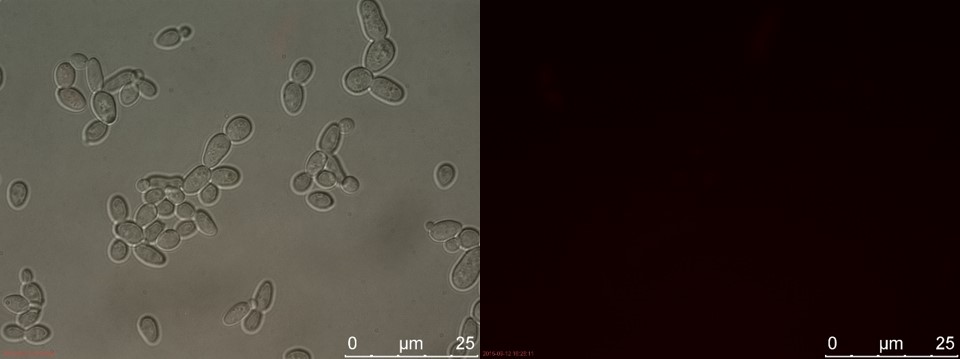
Figure 12. TEFSUC sample 1 cultivated for 2 hours. Left: overlay channels (bright field, RFP and GFP). Right: RFP channel.
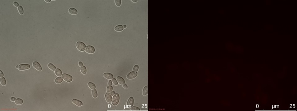
Figure 13. SUC sample 1 cultivated for 2 hours. Left: overlay channels (bright field, RFP and GFP). Right: RFP channel.
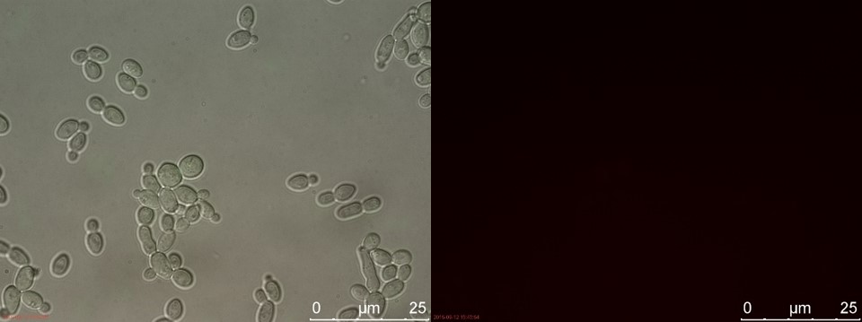
Figure 14. WT sample 1 cultivated for 2 hours. Left: overlay channels (bright field, RFP and GFP). Right: RFP channel.
3 hours of cultivation in YPD (after overnight preculture) gives no visible RFP fluorescence. A reason for this could be that 2 hours is not enough to give a significant drop in energy levels to relieve the repression of pSUC2.
A new sample of TEFSUC, SUC and WT was cultivated for 6 hours in YPD. The results from fluorescent microscopy are shown in figure 15-18.

Figure 15. Positive control. Left: overlay channels (bright field, RFP and GFP). Right: RFP channel.
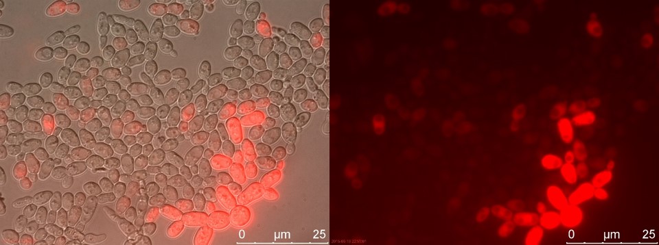
Figure 16. TEFSUC sample 2 cultivated for 6 hours. Left: overlay channels (bright field, RFP and GFP). Right: RFP channel.
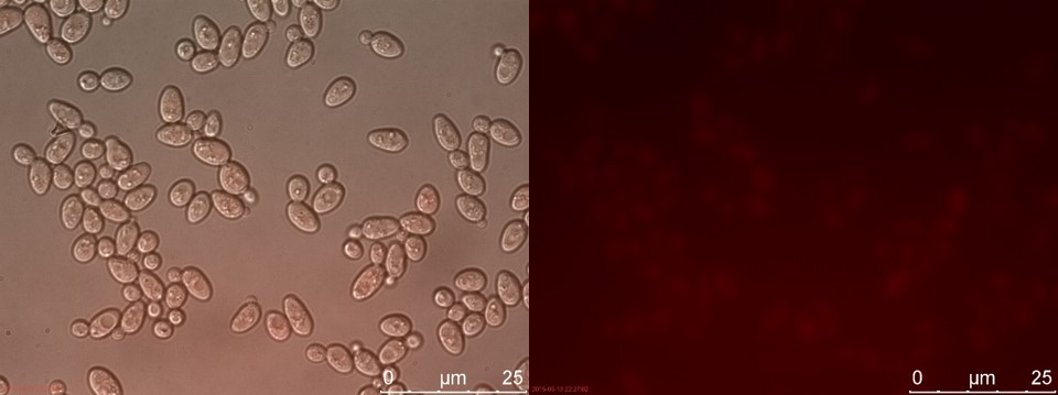
Figure 17. SUC sample 2 cultivated for 6 hours. Left: overlay channels (bright field, RFP and GFP). Right: RFP channel.
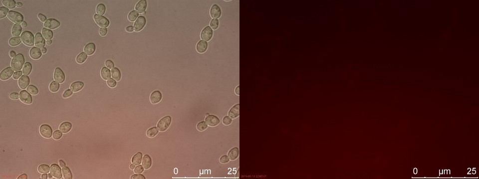
Figure 18. WT sample 2 cultivated for 6 hours. Left: overlay channels (bright field, RFP and GFP). Right: RFP channel.
Now there is a clear difference between TEFSUC and SUC. TEFSUC gives several highly fluorescent cells while SUC only shows slightly higher fluorescent compared to WT. This indicates that the repression of pSUC2 is reduced which allows expression of mRFP through the high expression promoter pTEF1.
Another fluorescence measurement was performed on the same sample after 23 hours of cultivation. The results from fluorescent microscopy are shown in figure 19-22.

Figure 19. Positive control. Left: overlay channels (bright field, RFP and GFP). Right: RFP channel.
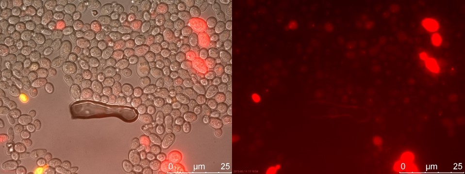
Figure 20. TEFSUC sample 2 cultivated for 23 hours. Left: overlay channels (bright field, RFP and GFP). Right: RFP channel.
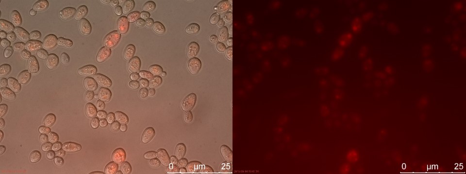
Figure 21. SUC sample 2 cultivated for 23 hours. Left: overlay channels (bright field, RFP and GFP). Right: RFP channel.
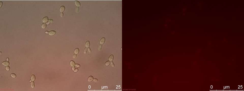
Figure 22. WT sample 2 cultivated for 23 hours. Left: overlay channels (bright field, RFP and GFP). Right: RFP channel.
This demonstrates that the concept of this safety switch could work, but the lethal gene has to be changed to a more potent one to be classified as a functional safety switch
