Difference between revisions of "Team:IISER Pune/Modeling"
| Line 8: | Line 8: | ||
==Tables== | ==Tables== | ||
| − | {| class="wikitable" style="text-align: center | + | {| class="wikitable" style="text-align: center;background-color:rgba(255,244,238,0.5)" |
|+ Introduction to variables: | |+ Introduction to variables: | ||
| + | | style="caption-side:bottom" | ||
| + | |"Table2.1" | ||
|N | |N | ||
|Cell density at given point of time | |Cell density at given point of time | ||
Revision as of 18:43, 20 November 2015

Contents
Tables
| style="caption-side:bottom" | "Table2.1" | N | Cell density at given point of time |
| Nm | Carrying capacity | ||
| k | Growth rate constant | ||
| E | Concentration of toxin | ||
| A | Concentration of AHL | ||
| kE | Production rate of toxin | ||
| dE | Degradation rate of toxin | ||
| kA | Production rate of AHL | ||
| dA | Degradation rate of AHL | ||
| d*E | Death rate of cells |
Images
Introduction
Mathematical modeling suffices to –
- Provide an objective view towards complex & apparently diverse systems. This objectivity is instrumental for efforts motivated by the idea of generalization.
- Provide an ability to predict the behavior of a system i.e. to predict the properties of a state of the system given the information for some other state.
Simulations–
- Give us a way in which the numbers mimic biological/chemical ‘characters’ & equations derive their behavior.
- Help us in visualizing the results of equations that are analytically unsolvable.
Here, with the instruments of ODEs, two biological circuits were modeled (and solved!)
- Variable-link Oscillator - Hijack Module
- Killer gene Circuit – Termination Module
Software & Methods
For solving the ODE (Ordinary Differential Equations) – Python 2.7.10 was used. We have used the Anaconda (Python distribution) for running all our scripts.
Initially we wrote our own implementation of Euler’s method of integration to solve all the systems of equations.
But after learning about scipy.integrate module we have been using Scipy's odeint function for integrating the ODEs
Scipy [version 0.15.1]
Modelling
Variable-link Oscillator
Description of oscillator
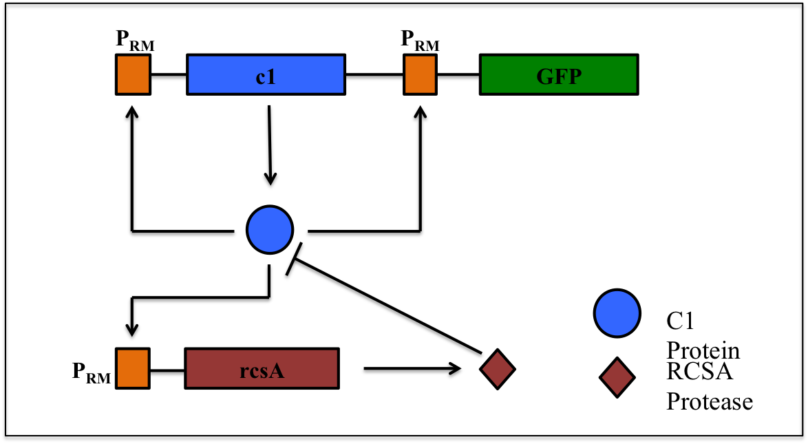
This is a synthetic genetic oscillator, operative in bacteria, first described by Hasty et. Al (ref. 1). The regulation here is based on protein- protease interaction between cI (protein responsible for maintaining lysogenous state in acteria infected with lambda phage) & rcsA (bacterial protease specific to cI). The cI protein acts as an auto-activator & an activator for production of rcsA while rcsA acts for degradation of cI, after a certain concentration of cI has been achieved. Hence, the concentration of cI exhibits oscillations. The behavior of these oscillations can be enquired when a visible reporter (like GFP) is incorporated in the network.
The basic requirement of the network is that all the genes- the cI gene, the rcsA gene & the gfp gene, should be present under the activity of same promoter – PRM (the natural promoter of cI in lambda phage).
The original model
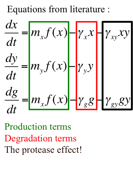
The model for this oscillator is formulated in the form of system of coupled ODEs.
Introduction to variables –
x = [CI]
y = [RCSA]
g = [GFP]
mx = copy number of plasmid containing cI gene
my = copy number of plasmid containing rcsA gene
γx = rate constant for natural degradation of cI
γy = rate constant for natural degradation of rcsA
γg = rate constant for natural degradation of gfp
γxy = rate constant for natural degradation of cI due to protease activity
γgy = rate constant depicting no depletion in production of gfp as a consequence of protease activity on activator - cI
f(x) = function determining production of gene under promoter PRM
α = Factor depicting enhancement in transcription
σ1 = Coefficient for binding of cI to OR2 relative to OR1
σ2 = Coefficient for binding of cI to OR3 relative to OR1
PRM promoter has three operator sites- OR1, OR2, OR3 to which CI-dimer binds sequentially. Binding of CI to OR2 enhances transcription & that to OR3 represses transcription.
Assumptions of Model –
- The cI gene along with reporter (gfp) gene is present on one plasmid, say – x, with plasmid copy number – mx, while the rcsA gene is present on another plasmid, say – y, with plasmid copy number – my . The oscillator is actualized as a two-plasmid system.
- (Major assumption)
mx > my
This assumption is responsible for maintaining the oscillatory nature of the system. - Reactions like transcription & normal degradation are slow & irreversible. Degradation is essentially due to growth.
Our work
Imitation
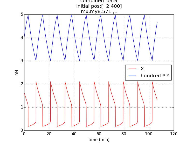
Reproduction of result- to be able to show oscillations (in x & y; here g is not considered separately since its behavior would be similar to that of x) through simulation has been possible by employing specific parametric values referred from literature (ref.1, ref.2).
Conditions for simulation:
Table 1.1
| Parameter or a constant | Value |
|---|---|
| x-initial conc. | 4 nM |
| y-initial conc. | 200 nM |
| mx | 10 |
| my | 1 |
| γx | 0.1 |
| γy | 0.01 |
| γxy | 0.1 |
| α | 11 |
| σ1 | 2 |
| σ2 | 0.08 |
Oscillations (according to model equations) of period of about 1o minutes were obtained on simulating the specified conditions.
Investigation
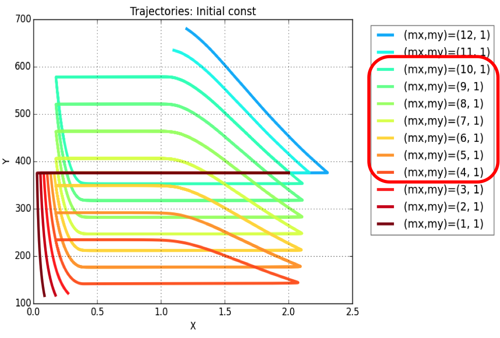
Plasmid copy number is an evident parameter when tunability of the oscillator is considered. Keeping the values of all other variables constant, simulations were run for exploring those values of mx & my, for which system exhibits oscillatory regime.
The simulation leads to conclusion that oscillations are possible for a range of plasmid copy number ratio (mx : my) values as marked in the legend of the plot. Oscillations (of varying amplitudes & periods) occur between mx : my = 4:1 & mx : my = 10:1.
Innovation
Employing this oscillator in our genetic device is possible only at the cost of violating the major assumption of this model- mx > my . This is because our entire genetic device needs to be packaged in single plasmid vector & hence, two plasmid based oscillator is not feasible.
This problem led to development of alternative strategies to create a single plasmid based oscillator. The basic idea behind these strategies is to exploit other parameters like- RBS efficiency, number of gene sets etc. to achieve the same numerical ratio for which oscillatory regime exists.
Alternative strategies :
- Multiple promoter sites (i.e. gene sets)-
- Disadvantages of this alternative :
- Not “effective” as plasmid copy no. ratio
- Possible problems arising due to promoter titration
- Requirement of larger plasmids
- Disadvantages of this alternative :
- Different RBS Efficiency ratios-
- Advantages of this alternative :
- Present as bio-bricks (measurements performed)
- Efficiency ratios comparable in magnitude to copy no. ratio (from 4:1 to 10:1)
- Advantages of this alternative :
-
Combinatorial way-
(no. of gene sets) * (RBS efficiency ratio) ≅ plasmid copy no.
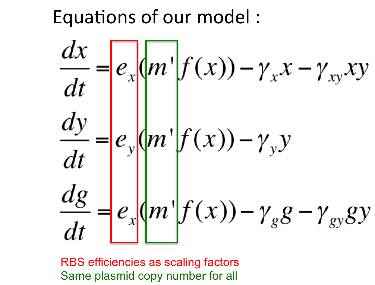
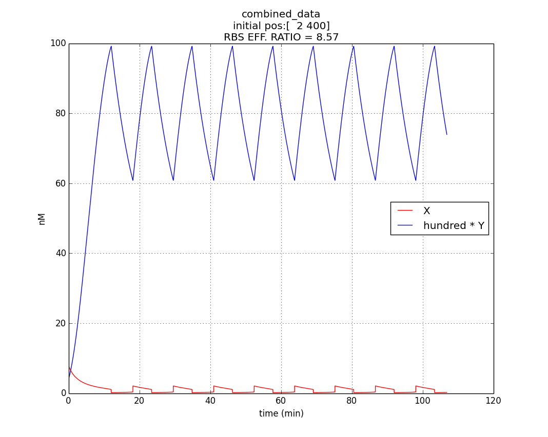
Here, our model is an oscillator that exploits the difference in the translational efficiencies of different ribosome binding sites (RBSs).Our model makes use of existing, well characterized RBSs (present as bio-bricks) whose efficiencies are known.
Introduction to new variables : ex = RBS efficiency of RBS associated with cI gene
ey = RBS efficiency of RBS associated with rcsA gene
m’ = plasmid copy number of the ‘single’ plasmid (containing entire oscillator)
Assumptions of our model :
The simulation run :
Conditions for simulation
Table 1.3
Parameter or a constant |
Value |
|---|---|
| 0.6 | |
| 0.07 | |
| m'(=mx' =my' ) | 10 |
Keeping all other parameters at same values as in Table 1.1
Hence, ex : ey = 0.6 : 0.07 = 8.75 : 1 (which is between 4:1 & 10:1 numeric ratio values)
The simulation run for specific RBS efficiency ratio, keeping all other parameters consistent with the first simulation, resulted in oscillations of period- 10 minutes. Hence, efficient oscillations are shown by our model with respect to period (which is crucial to our genetic device).
Concluding Remarks
- Successful in reproducing the published results for variable-link oscillator.
- Successful in exploring the parametric range for which oscillatory regime exists.
- Successful in building a general strategy for designing a single plasmid based oscillator.
- Successful in showing oscillations of a single plasmid based oscillator harnessing different RBS efficiencies.
References
1. Designer Gene Networks : Towards Fundamental Cellular Control -- J. Hasty & et.al.
2. Comparative analysis of synthetic genetic oscillators -- O. Purcell & et.al.
Quorum Sensing Termination Circuit
Introduction
The termination module to self destruct cells or cease further replication and thus to prevent uncontrolled growth is is necessity of our genetic device, considering the bio-safety of the whole project.
Background
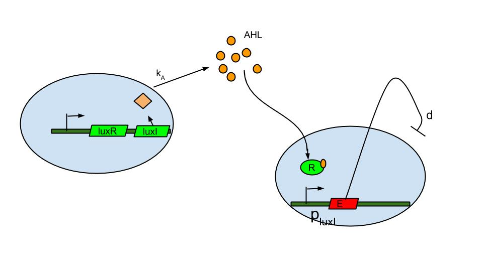
Quorum sensing is well known in the form of luxI/luxR system which was found in Vibrio fischeri a marine bacterium. The bacterium is known to release signaling molecule AHL (acyl-homoserine lactone) which diffuses across the cell membrane. As cell density increases AHL concentration increases in the extracellular medium and inside the cells. At high enough concentrations it binds to and activates LuxR, a transcriptional regulator which then induces the LuxI promoter causing the expression of fluorescent protein.
The basic termination model has been described and demonstrated earlier based on lux R-lux I system (ref.1). The system comprises of sender and receiver parts wherein, promoter of sender part is IPTG inducible. When the promoter is switched on.
- luxI production causes release of AHL .
- The AHL diffuses across cell membranes to nearby cells and binds to luxR.
- Activated luxR induces the plux I releasing the Ccdb toxin (E) that causes cell death.
Model
The first approach was to have the termination module switched on from the start, sending the AHL signals.
In this the model previously proposed (You et. al. 2004 ) was successfully reproduced(Approach 1). We then further modified it for our problem as discussed in Approach 2 and Approach 3.
Approach 1: Constitutive Expression
Our system is identical to the one already reported with the exception that promoter is assumed to be constitutive instead of IPTG inducible
In this approach we thereby also reproduce the results of the previously proposed model using simulations in python as follows.
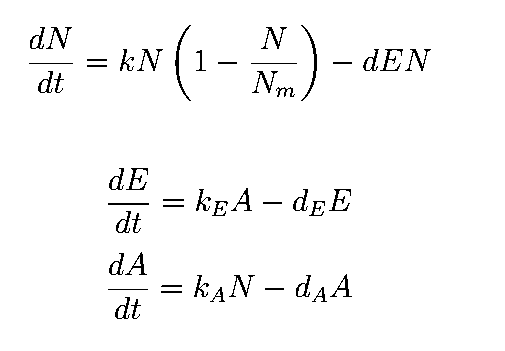
The equations describing the model are given as:
Equations from original model :
[[File:|none|200px|Equations]]
Table 2.1
The first equation is a modified logistic curve with an added death rate term (dEN).
The second equation describes the production of toxin(E) as linearly proportional to the AHL concentration and the third assumes that AHL(A) formed is proportional to the no of cells.
Both AHL and killer protein are assumed to degrade by first order kinetics with given rate constants.
Assuming the constitutive promoter of same strength as the IPTG inducible one there would be no change in KA .
We thus solve the ODEs for the initial condition (t=0) [N=1250 , A=0 ,E=0] .
The following values of parameters were used:
Table 2.2: Parameters for termination model (ref.1)
Table 2.3:Two sets of values of k , NM ,dA were used in different simulations.
The results shown (in Results section) for Approach 1 are for the values of k , NM , dA given in pH 6.6 column
Results
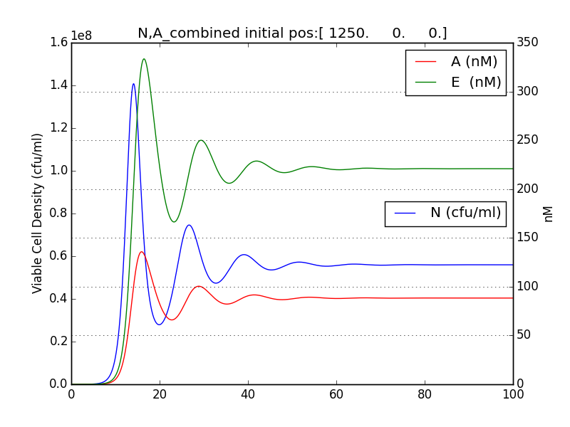
It was observed that terminator does not just act like a binary switch on the cell population.
The concentration of E and A also oscillate with decreasing amplitude similar to the population of cells.
Figure 2.3 Plot of N (Number of cells), A (AHL concentration), E (killer protein concentration)
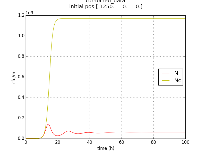
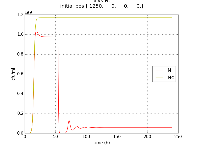
Figure 2.4 Comparison with a un-induced terminator population (Nc) (predicted using logistic kinetics ) showing extent of termination
This method/circuit of having killer gene under a constitutive/ (induced from start) does not solve our needs.
Problems:
- The population doesn’t reach a high enough population number (figure 5) from the beginning which unsuitable for the goal of IGEM IISER as detectability would be low.
- Ns := stable value of N is not appreciably low. The approach doesn’t send the population to zero (or even negligible) at large t.
- Population reduced by factor of about 20 only.
OurWork
Approach 2: Delayed termination
Based on the results of Approach 1 a delay term was introduced to allow the population to reach significant numbers initially . This was incorporated as “T” the time at which the terminator module is switched on.
T is an arbitrary time after population close to Nm is reached.
It was expected that by switching it on at a later time T(when the population is saturated) we would get better population growth initially(t<T) but since there would be more cells to terminate the post termination population would be higher (value between Nm and Ns) or it would take more time to reach the Ns population.
To mathematically simulate the scenario we broke it into two parts.
- Part 1 (t<T): Terminator circuit off.[Simple logistic curve is followed](already solved)
- Part 2 (t>T): Terminator circuit is switched on. This is same as the original problem with Ninit=Nm
Merging the solutions leads to the full solution.
The same values of parameters in Table 1 used in Approach 1 are used for this simulation. The results shown are for the values of k , NM , dA given in pH 6.2 column in Table 2.3.
Result
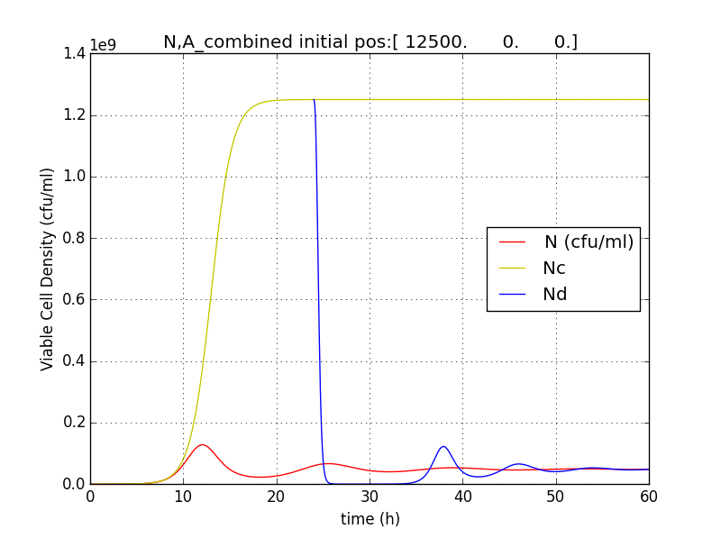
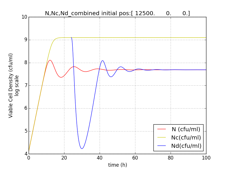
Figure 2.5 Terminator is switched on at T=24h. N (population with termination from start) Nd (Population of cells after terminator switched on at t=T) Nc (Population without terminator)
Figure 2.6 Plot showing population reduction by almost 5 orders
Problems:
- The population bounces back to normal levels after a while. It doesn’t reach zero or stay low.
The problem is inherent in the model as it forces an analytic solution of Ns for the number of cells at very large times (when t tend to infinite)
Advantages
- The population falls to a numbers significantly lower (figure 2.6) than the values of the previous (constitutive) scheme for a period after terminator is triggered. This is similar to a switch like terminator we had wanted.
Therefore the delayed termination is a better strategy for termination than constitutive expression.
Approach 3: Pigment initiated termination
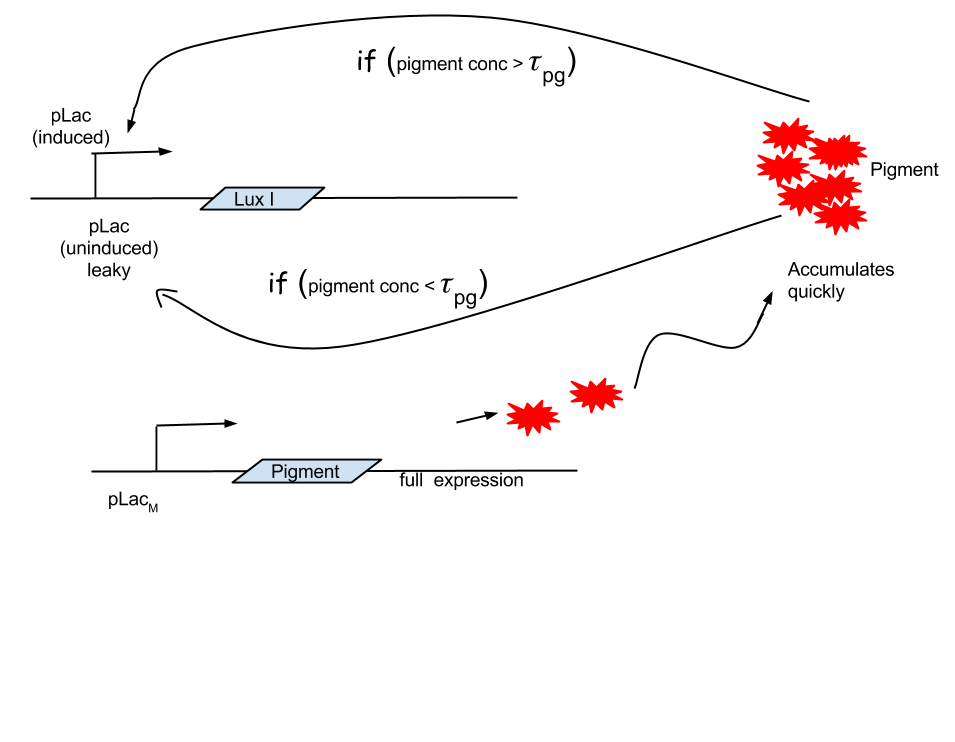
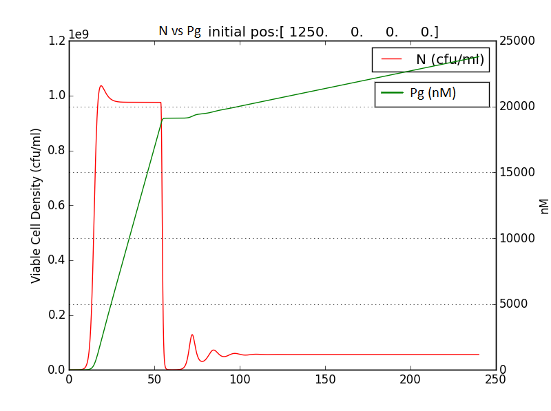
Looking at the results of Approach 2 where the delayed termination was seen to be more effective, we decided to couple it with the detection module such that the killer gene is activated when a certain concentration of pigment is reached. Our new modified module is as follows
The pigment production gene is under a constitutive promoter producing pigment from the beginning.
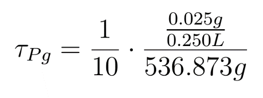
When certain threshold pigment concentration (τPg) is achieved, the terminator is switched on.
Figure 2.2 Schematic showing pigment threshold initiated terminator
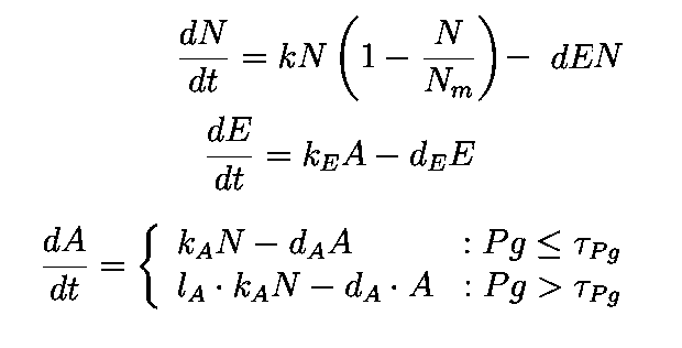
Here our assumption is that the pigment production is proportional to number of live cells.
The equation for this is:

==
![The centre gear[loading..]](https://static.igem.org/mediawiki/2015/2/23/IISER_PUNE_Gear_big_white_2.5.svg)
![The side gear[loading..]](https://static.igem.org/mediawiki/2015/9/93/IISER_PUNE_Gear_small_white_2.5.svg)
![Logo[loading..]](https://static.igem.org/mediawiki/2015/8/8b/IISER_PUNE_Gear_Logo.svg)
