Team:EPF Lausanne/Project/Description
Gate designs
Logic Gate
The first step in creating a biological circuit is to imitate the way the electrical signal is processed. A low voltage (or absence of signal) corresponds to the “0” signal and a high voltage (or presence of signal) to the “1” signal. In the Bio LOGIC design, there are no “low” or “high” signals. Both the “0” and the “1” signals are represented by specific gRNAs and it is promoters that work as transistors.
Logic gates have the ability to receive an input (for instance a “1” and a “0” signal) and to produce a specific output (for instance signal “1”) using transistors.
We explain here how our three Bio LOGIC NAND gate designs (simple, medium and complex) make this processing possible using biologic components: dCas9 (the wires), promoters (the transistors) and gRNAs (signals “0” or “1”).
| \(A_\text{input}\) | \(B_\text{input}\) | \(C_\text{output}\) |
|---|---|---|
| \(A_0\) | \(B_0\) | \(C_1\) |
| \(A_0\) | \(B_1\) | \(C_1\) |
| \(A_1\) | \(B_0\) | \(C_1\) |
| \(A_1\) | \(B_1\) | \(C_0\) |
Gate simple

Let us begin with the first NAND gate design: the simple design. The input gRNAs are A and B, and they can represent either a “1” signal (A1, B1) or a “0” signal (A0, B0). The output gRNAs is either C1 (for an output signal “1”) or C0 (for an output signal “0”). In order to make the gate testable, we replaced gRNA C0 by a RFP and gRNA C1 by a GFP.
We will go step by step through all four lines of the truth table on the right.
First line: if A0 and B0 are expressed, promoter 1 is activated, therefore expressing C1, but promoter 2 is repressed. Therefore C0 is not produced, and the ouput is C1.
Second line: if A0 and B1 are expressed, promoter 1 is activated thus producing C1. But promoter 2 is repressed, because repression prevails on activation (A R results in the same state as R). Therefore C0 is not produced, and the output is C1.
Third line: A1 does not bind anywhere on promoters 1 or 2, and therefore does nothing. But B0 activates promoter 1, thus producing C1: the final output.
Fourth line: A1 does not bind anywhere on promoter 1 and 2, and therefore does nothing. But B1 activates promoter 2, thus producing C0: the final output.
We just went through the truth table of a biological NAND gate.
Gate medium

Now let’s continue with the second gate design: the medium design. This time, the signal is processed by three promoters (or transistors) instead of two in the simple design. Again, we will go through all lines of the truth table.
First line: if A0 and B0 are produced, promoter 1 is repressed, promoter 2 is repressed (because repression prevails over activation) and promoter 3 is activated, thus producing C1: the final signal.
Second line: if A0 and B1 are produced, promoter 1 is repressed (because repression prevails over activation), promoter 2 is activated, thus producing C1 and promoter 3 is repressed. Therefore, the final signal is C1.
Third line: A1 does not bind anywhere on promoters 1, 2 or 3 and therefore does not do anything. B0 represses promoter 2 and activates promoter 3, which produces C1: the final signal.
Fourth line: A1 does not bind anywhere on promoters 1, 2 and 3 and therefore does not do anything. B1 activates promoter 1, thus producing C0 and represses promoter 3. Therefore, C0 is the final signal.
Gate complex

The third design, the most complex of the three designs avoids basal expression levels. Indeed, in the the simple and the medium design, the gRNA specific sequence A1 is not present on any of the promoters. Therefore had to assume that the basal level of the promoters will not produce a strong enough output to compete with the intended output.
The complex design theoratically solves this problem, as all promoters are always either activated or repressed.
Let’s go one last time through the four lines of the truth table.
First line: if A0 and B0 are produced, promoter 1 is repressed, promoter 2 is repressed but promoter 3 is activated, thus producing C1: the final signal.
Bio LOGIC in 12 questions
What does Bio LOGIC stand for?
It stands for "Bio Logic Orthogonal gRNA-Implemented Circuit”. In a few words, we are working on implementing digital-like circuits in cells using dCas9.
Don’t biological circuits already exist?
Yes. However, difficulties in the multiplication and chaining of logic elements has hindered the complexification of these circuits. To overcome these limitations, an ideal in vivo logic element should be modular, reusable and orthogonal - i.e. avoiding cross-talk with its host organism and the other elements of the circuit.
So, what’s different about your system?
We can avoid some of these issues by making a completely synthetic biological circuit. This is what we are doing by using the newly discovered dCas9 as a synthetic transcription factor.
How can dCas9 be used as a transcription factor?
Well, you know CRISPR-Cas9, the RNA-guided DNA endonuclease, right? (Check out the Background tab for more information about CRISPR-Cas9.) We are using dCas9, the catalytically dead version of Cas9, which lacks the ability to cleave DNA, but can still bind it. We fused dCas9 to a RNA Polymerase (RNAP) recruiting element. Depending on where it binds, it will either activate or inhibit transcription.


How does this activation/inhibition system work?
When dCas9 binds at an optimal distance upstream from a promoter, the RNAP recruiting element with which it is fused will, in fact, recruit RNAP, thus activating the transcription of the gene that is controlled by this promoter. However, when dCas9 binds close to the transcription start site, it will sterically hinder RNAP from binding at the transcription starting site, thus inhibiting the transcription of the gene.
How do you guide the dCas9 to activating/inhibiting region?
dCas9 works just like Cas9, meaning it is RNA-guided. Guide RNA (gRNA) and dCas9 can form a complex. This complex will bind tightly to a DNA sequence which is complementary to the gRNA specificity determinant sequence. So we can guide dCas9 to activating or inhibiting regions of a promoter by producing adequate gRNAs.
Can a gRNA-dCas9 complex activate one region and inhibit another in the same cell?
Yes, a gRNA-dCas9 complex will bind to any sequence that is complementary to the gRNA. So, if the activating region and the inhibiting region of different promoters have the same sequence, two identical gRNA-dCas9 complexes can bind both at the same time. This is also why we have to be careful not to target regions that are present in the genome of the host organism, in order to avoid interfering with other cellular functions.

What happens if the activating region and the inhibiting region of the same promoter are bound by dCas9 at the same time?
That is a very good question! It was shown that inhibition is dominant in S. cerevisiae (yeast) [1]. This means that, if both activating and inhibiting regions are bound, transcription will be inhibited, RNAP is recruited but steric hindrance still prevents its binding. One goal of our project is to find out if this is also the case in E. coli (bacteria). We will also test our system in yeast.
How are you going to use this to make biological circuits?
Because of time constraints, we were not able to make a real biologic circuit. We aim to make and characterize a biological equivalent to the simplest element in a digital circuit, a transistor. Transistors function like controllable switches for electric current. Our bio-transistors work like switches for the transcription of a gene and can be assembled to form biological circuits.
What does your bio-transistor look like?
The bio-transistor is a synthetic promoter with a gene output, but regulated in a novel way. We insert this synthetic sequence in a cell, along with a gene producing dCas9 fused to a RNAP recruiting element and a sequence that produces a gRNA complementary to either the activating or the inhibiting region of the promoter. dCas9 and the gRNA are produced, they form a complex which binds to the activating or inhibiting region of the promoter, thus “turning the gene on or off”. Because the "off" state prevails over the "on" state, its behaviour mimicks that of an electronic PNP transistor.
How do you make biological circuits from bio-transistors?
Well, digital circuits are made out of logic gates, elements that perform basic logic functions (AND, OR, NOT, NOR, NAND, XOR, etc.), and logic gates are made out of transistors. Our idea is to assemble our bio-transistors into logic gates. By linking the output of one logic gate to the input of another, we can make biological circuits that function in the same way as digital circuits.
Sounds cool! But what can this be used for?
A single transistor is not very useful. However, by assembling a certain number of bio-transistors, we could make more complex biological circuits that would have a wide range of outputs depending on many inputs. For example, we could make complex biosensors by building a circuit that is activated by the presence of a specific combination of molecules, or that has a different response for different combinations of molecules. This is only one example among the many applications of biological circuits.
Find out more about how we implemented our system in E. coli and in S. cerevisiae or about what’s already been done with biological circuits and the publications that inspired us, or check out our results.
References
[1] Farzadfard, F., Perli, S. D., Lu, T. K. (2013). Tunable and Multifunctional Eukaryotic Transcription Factors Based on CRISPR/Cas. ACS Synth. Biol., 2 (10), pp 604–613.
The story we are composing is the imitation of an electronic circuit, made of biological elements. Every biological element of this system has a role to play. Here are the members of the cast:
| Electronic transistor | Bio LOGIC in E. coli | |
|---|---|---|
| Connector | Electrical wires | dCas9-ω protein |
| Transmitted information | Electrical voltage either high or low | gRNAs either activating or repressing |
| Receptor of information | Entry of next transistor, the base | Promoter J23117 |
dCas9-ω as a connector
We will use the DNA-binding activity of the catalytically 'dead' version of Cas9, dCas9, to regulate genes.
For activation to be possible, dCas9 needs to be fused to a RNA polymerase (RNAP) recruiting element. We fused the ω (omega) subunit of RNAP to dCas9 [1]. The ω subunit works as a RNAP recruiting element in E. coli when working in a strain in which RNAP lacks the ω subunit. We used JEN202, "an E. coli MG1655 mutant in which rpoZ, encoding for the ω subunit of RNAP, was replaced by a Spectinomycin resistance gene" [1], for all fluorescence measurements.

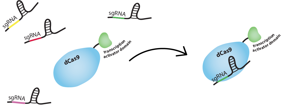
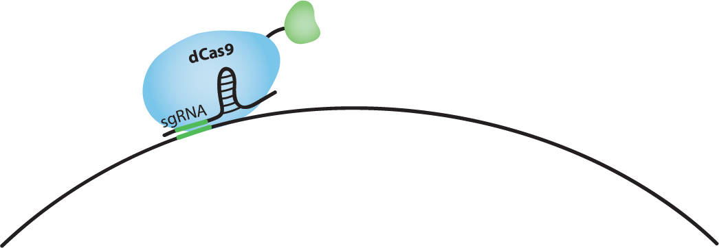
sgRNAs as the transmitted information
We used single guide RNAs (sgRNA) to guide dCas9-ω to targeted regions flanked by a PAM sequence. An sgRNA "comprises a complementary domain that binds to the DNA followed by a “handle” that is bound by dCas9" [3]: in our case dCas9-ω. dCas9-ω and an sgRNA form a complex which will tightly bind a DNA sequence complementary to the 'complementary domain' of the sgRNA.
Find out how we regulate genes with dCas9-ω below!
The bio-transistor
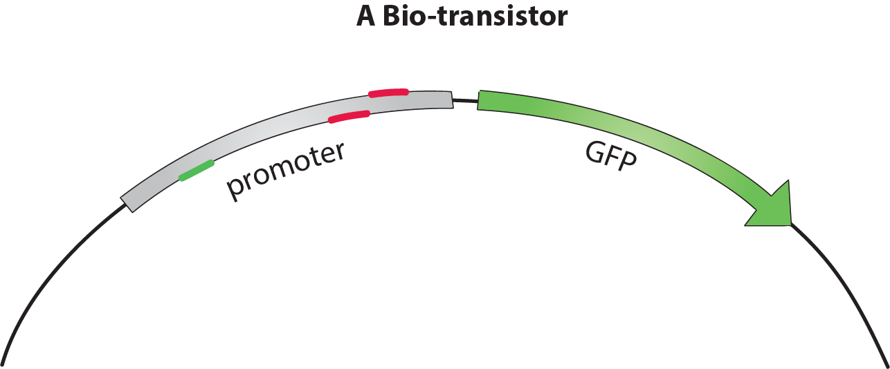
The bio-transistor for E. coli consists of a gene controlled by a synthetic promoter.
We synthesized promoters based on the constitutive promoter J23117 [1]. This promoter consists of BBa_J233117, preceded by a protospacer-adjacent motif (PAM) rich upstream regulating sequence (URS) [4].
To show that the bio-transistor works with different promoter sequences, we tested our system for the promoters J23117 and J23117_alt. The sequence for J23117_alt was randomly generated, except for the -35 and -10 regions that were conserved from J23117. Some of our team members wrote a program in C++ and then in Python that generated this type of random sequence while conserving part of an original sequence.To observe the activity of a single bio-transistor, we used a gene encoding for green fluorescent protein (GFP) as a reporter gene.
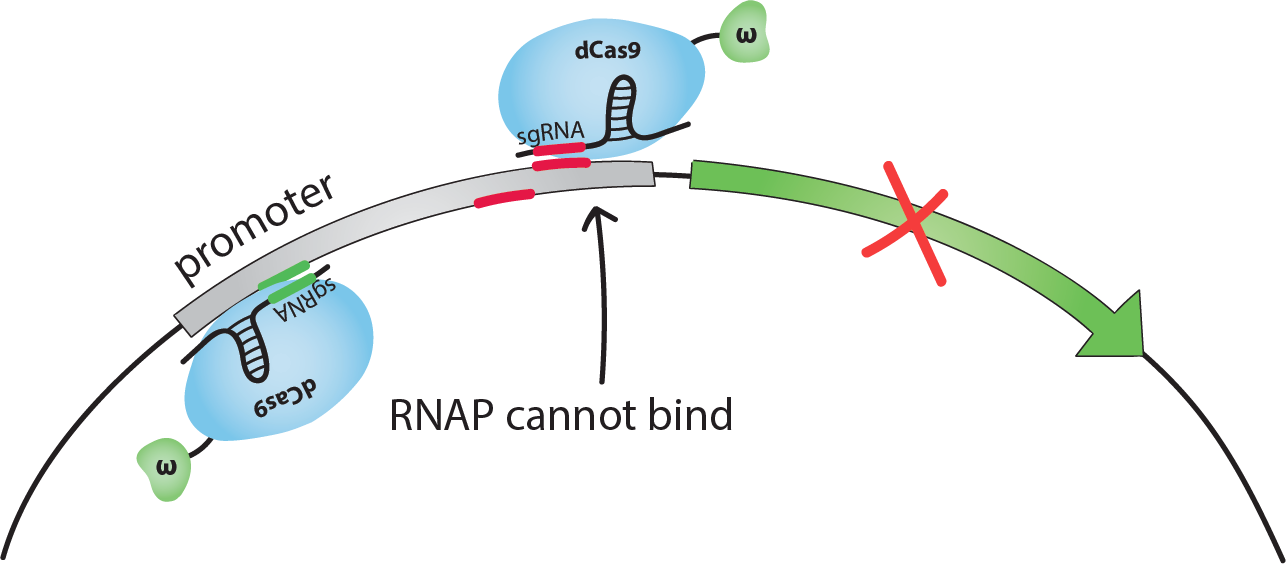
If dCas9-ω guided by an sgRNA binds on the promoter close to the transcription start site, the binding of RNAP to DNA is sterically inhibited, and transcription is repressed. We chose to use sgRNAs complementary to sequences 14 or 18 bp upstream from the transcription start site (TSS). We will call these the inhibiting sites -14 and -18.If dCas9-ω guided by an sgRNA binds at an optimal distance upstream from the promoter, the ω subunit recruits RNAP and transcription is activated. We chose to use sgRNAs complementary to the sequence 71 bp upstream from the TSS. [1]Note that the activating sgRNA and the -18 inhibiting sgRNA are complementary to the bottom strand of the promoter, whereas the -14 inhibiting sgRNA is complementary to the top strand.When generating sequences for the sgRNAs and the binding sites, it is important that they are not present in the host organism's genome to avoid regulating genes other than the targeted one.
If both one inhibiting and the activating sgRNA for the same promoter are present in the same cell, we foresaw 2 possible situations. We simulated both with our model: either dCas9-ω can bind both the activating and the inhibiting sites, in this case the model predicts that inhibition will tend to be stronger, or dCas9-ω cannot bind both sites due to steric hindrance in which case the overall effect should tend to be activating.For more information on these situations, check out our modeling page, or see how this turned out experimentally in our results!
We constructed plasmid pdCas9-ω, encoding for dCas9-ω regulated by a Tetracylcine-inducible promoter, from pdCas9-bacteria [2] and pWJ66 [1]. We synthesized 'sgRNA expressing cassettes' (IDT) controlled by the constitutive promoter pBad and inserted these into pdCas9-ω. We inserted either 1 or 2 sgRNAs (combinations of 1 activating and 2 inhibiting, affecting the same promoter).We used pWJ89 [1], GFP controlled by the J23117 promoter, [1] as a 'reporter-transistor'. We constructed a 2nd 'reporter-transistor' called pWJ89_alt, GFP controlled by the J23117_alt promoter, from pWJ89 and J23117_alt (synthesized by IDT).Find out more about the construction of these plasmids in our Lab Notebook!
We transformed JEN202 cells with one of the 'reporter-transistors' and pdCas9-ω with sgRNAs complementary to the activating and/or inhibiting regions of the promoter of the transistor, and measured the fluorescence of these cells with a plate reader or by flow cytometry. After trying several concentrations of Anhydrotetracycline (ATc), we decided to do all further experiments with 1 ng/mL ATc.Take a look at our results here!


Inducible bio-transistors

In a biological circuit, the production of the sgRNAs would most likely be induced, instead of constitutive. To test this with our bio-transistors, we changed the promoter of the 'sgRNA expressing cassette' to make it inducible. We did this by inserting a 'sgRNA expressing cassette', controlled by constitutive promoter pBad, in a plasmid containing AraC, placing the pBad promoter next to AraC. When placed next to one another, AraC is a repressor of pBad, and pBad can be induced by adding Arabinose to the medium [5]. Thus, the production of this sgRNAs becomes inducible with Arabinose.
We constructed three plasmids in this fashion with sgRNAs complementary to the J23117_alt promoter: one with the activating sgRNA controlled by pBad/AraC, one with one of the inhibiting sgRNAs controlled by pBAd/AraC, and one with the same inhibiting sgRNA controlled by pBad/Arac and the activating sgRNA controlled by pBad (constitutive).Find out more about the construction of these plasmids in our Lab Notebook!
We transformed JEN202 cells with the 'reporter-transistor' with J23117_alt promoter, pdCas9-ω and one of the pBad/AraC constructs, and (again) measured the fluorescence of these cells with a plate reader or by flow cytometry. We kept ATc levels at 1 ng/mL and tested 0 mM, 0.1 mM, 1 mM, 10 mM Arabinose.See how this worked out on our results page.
Linking bio-transistors
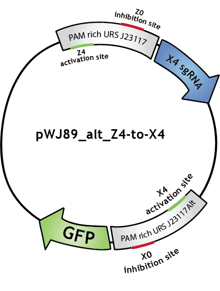
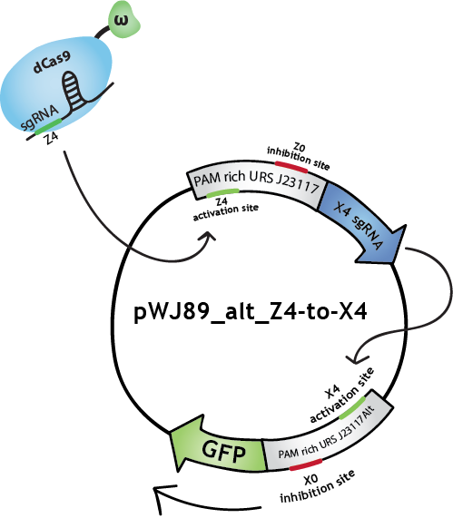
To make biological circuits with our bio-transistors, we will have to link several bio-transistors. To test whether the "signal" is strong enough for this to be possible with our system, we modified the transistor with promoter J23117 to express the sgRNA complementary to the activating site of J23117_alt, instead of GFP. In this way, when the first transistor (J23117) is activated by dCas9-ω bound to the corresponding sgRNA, another sgRNA will be expressed. This sgRNA, in complex with dCas9-ω, will bind the activating site of the second transistor (J23117_alt) which will activate the transcription of GFP. In an ideal situation, we would like to see that fluorescence levels obtained like this are close to levels obtained when simply activating one transistor.
We constructed this in one plasmid that we called pWJ89_alt_Z4-to-X4 by inserting the J23117 promoter followed by an 'sgRNA expressing cassette' (synthesized by IDT) into pWJ89_alt, the plasmid that contains GFP controlled by J23117_alt.You can find out more about the construction of this plasmid in our Lab Notebook!
We transformed JEN202 cells with pWJ89_alt_Z4-to-X4 and pdCas9-ω with different 'sgRNA expressing cassettes', notably the one expressing the sgRNA that will activate J23117. We kept ATc levels at 1 ng/mL.See the results here.
Note that in the Lab Notebook and in the figures the sgRNAs (and the corresponding binding sites on the promoters) have specific names:sgRNA activating J23117 and J23117_alt respectively: Z4 and X4. sgRNA -14 inhibiting J23117 and J23117_alt respectively: Z0 and X0. sgRNA -18 inhibiting J23117 and J23117_alt respectively: Z35 and X35
The logic gate
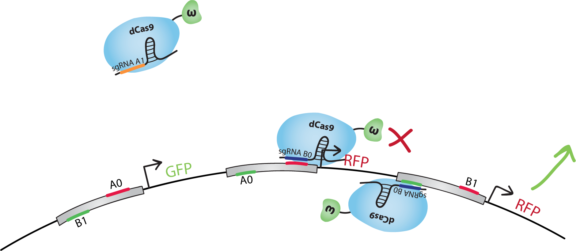
In digital circuits, transistors are assembled to form logic gates [6], which can then be linked to form complex circuits. Based on this, we decided to assemble our bio-transistors to form a (bio)logic gate. Below is our design for the NAND gate [7]. It corresponds to the "gate simple" design described in the "Gate designs" tab.

The design of our NAND gate contains 3 bio-transistors. The inputs, A and B, are in the form of sgRNAs called A0, A1, B0 and B1.Note that in our model the sequence A1 is not present in the transistors. dCas9-ω will bind to A1 but it will not find a binding site on the DNA.The output, C, is the transcription of GFP for C=0, and RFP for C=1.
We did the following design with the hypothesis that when activating and inhibiting sites of the same promoter are bound by dCas9-ω, the overall effect will be inhibition. We also suppose that, when neither the activating nor the inhibiting sites are bound, the basal transcription level is similar to the inhibited level.Note that many other designs of this gate are possible, and that with similar systems we could also reproduce other gates, such as NOT, AND, OR, NOR, XOR, etc.

Let's go through the first line of the truth table together. Note that all lines of the truth table is illustrated below.Let's start with A=0 and B=0. dCas9-ω will bind the inhibitory site of the 1st transistor. Transcription of GFP, C=0, will be at level 'i' (inhibited). dCas9-ω will bind both the inhibiting and the activating site of the 2nd transistor. Transcription of RFP(1), C=1, will be at level 'a/i' (activated and inhibited at the same time), which we suppose is equivalent to level 'i'. dCas9-ω will also bind to the activating site of the 3rd transistor. Transcription of RFP(2), C=1, will be at level 'a' (activated). If we consider 'i' levels of transcription to be negligible, we have a final result of an 'a' level of RFP transcription, ie. we have C=1 just like in the truth table.You can find a summary of the transcriptional response of the NAND gate in the 3rd column of the truth table below.


| Input A | Input B | Output: [GFP]->C=0 [RFP1, RFP2]->C=1 | Output C |
|---|---|---|---|
| 0 | 0 | [i] [a/i, a]≈[i, a] | 1 |
| 0 | 1 | [a/i]≈[i] [a, i] | 1 |
| 1 | 0 | [b]≈[i] [i, a] | 1 |
| 1 | 1 | [a] [b, i]≈[i, i] | 0 |
Due to time constraints, we were not able construct this gate and test it in the wet lab. However, modeling allowed us to qualitatively assess the functionality of logic gates in silico. After tuning some constants in order to reproduce basic activation and inhibition of a single transistor, we were able to reproduce more complex experiments (chaining two transistors, and simultaneous activation and inhibition). Finally, we were able to study the response of full logic gate, particularly the NAND gate.To find out more, take a look at our modeling page and our results page!
References
[1] Bikard, D., Jiang, W., Samai, P., Hochschild, A., Zhang, F., & Marraffini, L. A. (2013). Programmable repression and activation of bacterial gene expression using an engineered CRISPR-Cas system. Nucleic acids research, 41(15), 7429-7437.[2] Qi, L. S., Larson, M. H., Gilbert, L. A., Doudna, J. A., Weissman, J. S., Arkin, A. P., & Lim, W. A. (2013). Repurposing CRISPR as an RNA-guided platform for sequence-specific control of gene expression. Cell, 152(5), 1173-1183.[3] Alec AK Nielsen & Christopher A Voigt (2014). Multi-input CRISPR/Cas circuits that interface host regulatory network. Molecular systems biology, 10(11), 763.[4] Addgene about protospacer-adjacent motif (PAM)[5]BBa_I0500: inducible pBad/AraC promoter[6] Wikipedia article on Logic gates[7]Wikipedia article on the NAND gate
The story we are composing is the imitation of an electronic circuit, made of biological elements. Every biological element of this system has a role to play. Here are the members of the cast:
| Electronic transistor | Bio LOGIC in S. cerevisiae | |
|---|---|---|
| Connector | Electrical wires | dCas9-VP64 protein |
| Transmitted information | Electrical voltage either high or low | gRNAs either activating or repressing |
| Receptor of information | Entry of next transistor, the base | Promoter CYC |
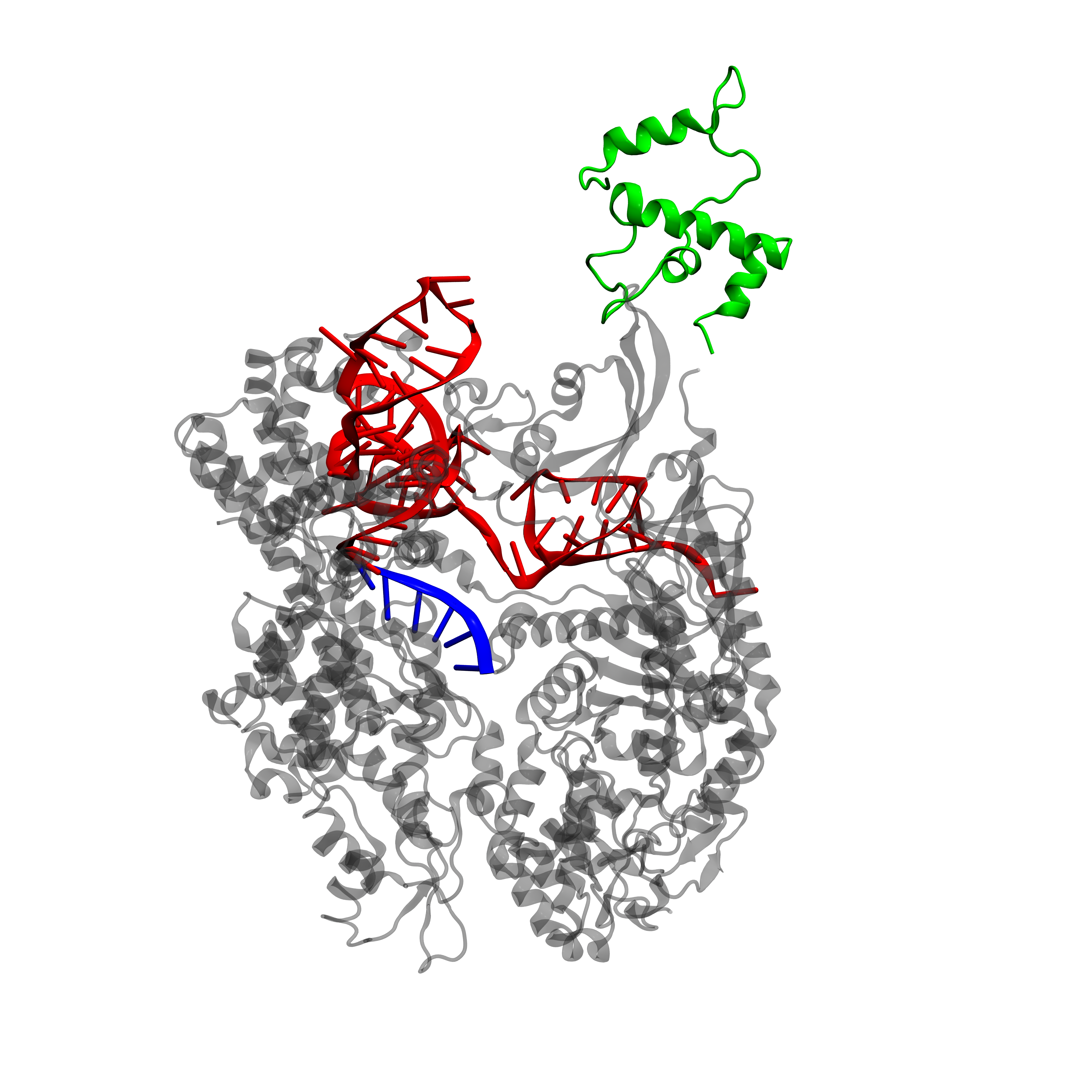
dCas9-VP64 as a connector
The dCas9 protein fused to a RNA Polymerase recruiting element, here VP64, can be used to activate or repress gene expression [1]. This regulation depends on the region of the promoter that dCas9-VP64 binds to.
gRNAs as the transmitted information
Each gRNA «cassette» is designed as in fig.1 :
5' - DsRed2 – polyA - HH ribozyme – gRNA SDS – gRNA scaffold – HDV ribozyme – 3'.
- DsRed2 is a fluorescent protein. It acts as a reporter gene for the production of gRNAs [1].
- The polyA tail is a sequence of 50 adenines. This particular sequence aims to replace the MATLAT1 triple helix in mammalian cells [3]. It increases translational efficiency [4] and contributes to efficient mRNA progression away from the gene [5].
- The hammerhead (HH) ribozyme and the hepatitis delta virus (HDV) ribozyme both carry out self-cleavage after transcription, [2] and [3].
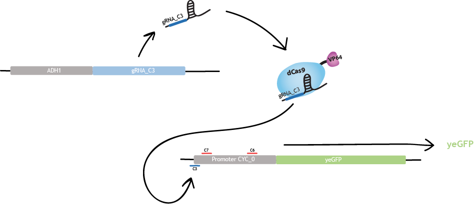
This design, under promoter ADH1, allows to recruit RNA polymerase II. This RNA polymerase allows production of multiple gRNAs from a single transcript, contrary to RNA polymerase III [3].

Bio-transistor
The gRNAs are sequences composed of a 20 nucleotides Specificity Determinant Sequence (SDS) and a 76 nucleotides scaffold. The 20 nucleotides SDS is complementary to a specific region of the promoter. It guides dCas9-VP64 to this specific region.

Gene expression is enhanced when the site targeted by dCas9-VP64 is located at the beginning or before the promoter, i.e. 25 nucleotides upstream from the TATA box and 50 nucleotides upstream from the transcrition start site. Gene expression is repressed when the targeted site is located on the promoter and in particular on the TATA box or the TSS region [1].
We use the region of strongest activation and the region of strongest repression.
The region of strongest activation is c3. Binding of dCas9-VP64 to region c3 produces a threefold increase of fluorescence [1].
The strongest repression is obtained with c6 and c7 simultaneously. The reason is that a stronger inhibition is observed when two gRNAs bind the promoter. Binding of dCas9-VP64 to c6 and c7 produces a sevenfold decrease of fluorescence [1].
Since we focus on three regions of the promoter, we use these three gRNA SDS : c3, c6 and c7. Each gRNA has four different exemplaries: c3_0, c3_1, c3_2, c3_3 for gRNA c3. The gRNAs c6 and c7 have the same notation. Each of these 20 nucleotides sequences are randomly generated by two programs, coded by us, in order to respect two conditions. First, the human blaster program ensures that gRNAs don't bind anywhere on the human genome for safety reasons. Second, another blaster program ensures that gRNAs don't bind anywhere in the genome of S. cerevisiae. We do not want our synthetic gRNAs to bind anywhere else than on the desired promoter.
A key challenge in engineering transcriptional networks is to design orthogonal transcription factors or promoters. This means gRNAs must not interfere with one another. It has been shown that a single base-pair mismatch between the gRNA SDS and the promoter region is sufficient to prevent the binding of dCas9-VP64 [1]. We ensured to avoid cross-talking issues by synthesizing gRNA SDS that are very different from one another, differing by at least 10 nucleotides out of 20.
Linking bio-transistor
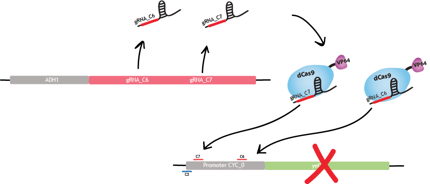
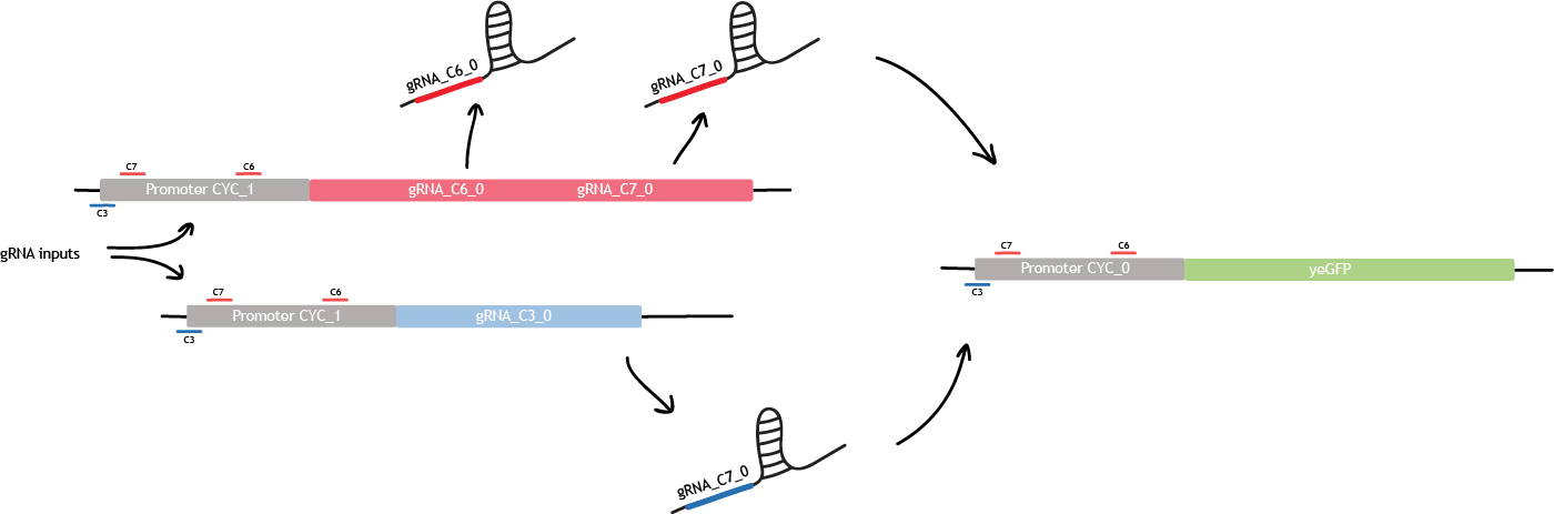
Building a bio-transistor consists in activating or repressing the expression of a reporter gene, GFP here. Linking the bio-transistors means replacing the expression of GFP by the expression of another gRNA.
This other gRNA will then bind the next synthetic CYC promoter, and will activates or repress the expression of GFP. This is the first level of linking.

Logic gate
The first level of linking allows to build one logic gate.For example, this is the NAND logic gate implemented in S. cerevisiae. We designed two more complex logic gates as seen under the tab "Gate designs" and in the section «Modeling». The design described below corresponds to the "Gate simple" design in "Gate designs".
References
[1] Farzadfard F, Perli SD, Lu TK. Tunable and Multifunctional Eukaryotic Transcription Factors Based on CRISPR/Cas. ACS Synth Biol. 2013 Sep 11. 10.1021/sb400081r PubMed 23977949
[2] Gao Y, Zhao Y. Self-processing of ribozyme-flanked RNAs into guide RNAs in vitro and in vivo for CRISPR-mediated genome editing. J Integr Plant Biol. 2013 Dec 30. doi: 10.1111/jipb.12152. 10.1111/jipb.12152 PubMed 24373158
[3] Nissim L, Perli SD, Fridkin A, Perez-Pinera P, Lu TK. Multiplexed and Programmable Regulation of Gene Networks with an Integrated RNA and CRISPR/Cas Toolkit in Human Cells. Mol Cell. 2014 May 14. pii: S1097-2765(14)00355-4. doi: 10.1016/j.molcel.2014.04.022. 10.1016/j.molcel.2014.04.022 PubMed 24837679
[4] [4] Preiss T, Muckenthaler M, Hentze MW. Poly(A)-tail-promoted translation in yeast: Implications for translational control. 1998 Nov;4(11):1321-31. PubMed : 9814754.
[5] Dower K1, Kuperwasser N, Merrikh H, Rosbash M. A synthetic A tail rescues yeast nuclear accumulation of a ribozyme-terminated transcript. RNA. 2004 Dec;10(12):1888-99. PubMed 15547135.
Background
Programmable cells - Promises and Limitations
The ability to process information is fundamental to life. Cells use complex gene regulatory networks to effectively respond to the myriad of signals they receive from both the outside environment and their internal metabolism. This information processing capability enables them to move around, communicate, reproduce - in one word, survive.
Since the early 2000s, researchers have sought to harness this capability by re-engineering cellular signal processing pathways for various biotechnology applications. By implementing rational, controllable logic elements in cells, researchers aim to transform living systems into engineered "machines" that may perform functions ranging from industrial production to biomedical therapies, bioremediation and energy production [1].
Up to date, various strategies and genetic parts have been used to implement information processing systems in cells. Many of these designs use the regulation of DNA expression as the adjustable signal in the circuit. A good example is the “repressilator†built by Elowitz et al. in 2000 that uses three orthogonal repressor-promoter pairs : LacI, tetR and λ cI to produce an oscillating signal [2]. Since then, multiple other repressors and activators (zinc-fingers, TALEs) have been used to target specific DNA sequences. Alternative strategies to engineer synthetic biological circuits are based on the control of RNA stability, RNA translation or protein-protein interactions as the basis for signal transmission.
The challenge today is to transition from the creation of small cellular genetic “devices†to cells that efficiently perform logical functions observed in electronic circuits. This issue calls for innovative strategies and rational design [3]. The engineering-driven approach of synthetic biology which includes parts standardization, modular components, modeling and systematic strategies to create biological circuits with reliable and predictable behaviors - holds part of the solution. The other key to the problem is to increase the number of orthogonal genetic components that may be used for signal processing [4]. The characterization of new parts that do not cross-talk with the cellular machinery nor with other parts of the genetic circuit promises to improve the robustness and efficiency of future circuits.
Retroactivity is not the only limitation of current cellular signal processing circuits. Such circuits are slow: their response time can be measured in hours or even days. Furthermore, they are often unreliable and offer low signal-to-noise ratios. Low output signal may make connecting multiple circuits impossible. Another limiting factor is the fact that the transcription factors used in the circuit may be toxic for the cell and that the circuit itself may monopolize the cell’s resources. Finally, circuit parts may behave unexpectedly in new genetic contexts [5]. These issues underline the huge task at hand when one dreams of transferring computing from a world of silicon into the realm of biology.

.png)
dCas9 to the rescue!
CRISPR stands for clustered, regularly interspaced, short palindromic repeat arrays. It plays the role of an immune system for bacteria by targeting and degrading foreign DNA. The CRISPR systems uses the Cas9 (CRISPR-associated) nuclease to introduce double-strand breaks to DNA sequences that are complementary to its guide RNA (gRNA). Catalytically dead Cas9 (dCas9) lacks the ability to cleave DNA and may act as programmable transcription regulator - by either preventing the binding of the RNA polymerase (RNAP) to the targeted DNA - or as an activator when it is fused to a RNAP recruiting element (the omega subunit of RNAP in E. coli and VP64 in Yeast) [7].
The main advantage of this system is that many different orthogonal pairs of synthetic promoters and targeting gRNAs can be designed. In addition, synthetic promoters may be built with numerous regulating binding sites in order to receive a variety of inputs, both activating and inhibiting. These properties make CRISPR a useful addition to the synthetic biologist’s toolbox. Its versatility may help build more complex and extendable genetic circuits, as has been already shown in recent publications. Indeed, this technology has been used to create simple logic circuits - such as NOR gates and 3-gate circuits [8].
Biological Transistors
Given the numerous advantages of this system, we decided to attempt to represent binary signals with the two 'elementary' CRISPR/Cas9- dependent operations described above. A system composed of Cas9 with appropriate sets of gRNAs and promoters should be able to act as an ON/OFF switch. In electronic circuits, the switches that control the flow of electricity are named transistors. In our circuit, the output, represented by the transcription of specific genes, is controlled by gRNA-targeted dCas9, where gRNA is the input. The promoter followed by a specific gene represents a transistor.Transistors are the fundamental building block of electronic circuits. Assembled into logic gates, they enable logic operations to be performed (the computation of true/false answers). Logic gates can be linked together to form complex digital circuits.
dCas9 may be used to build logic circuits that are orthogonal, modular and reusable. Such circuits should enable scientists to implement more complex logic functions in biological systems. We hope to explore the viability of dCas9 circuits as the transformative tool to rewire genetic networks it may well prove to be.
References
[1] Brophy, J. A., & Voigt, C. A. (2014). Principles of genetic circuit design. Nature methods, 11(5), 508-520.[2] A Synthetic Oscillatory Network of Transcriptional Regulators; Michael Elowitz and Stanislas Leibler; Nature. 2000 Jan 20;403(6767):335-8.[3] Purnick, P. E., & Weiss, R. (2009). The second wave of synthetic biology: from modules to systems. Nature reviews Molecular cell biology, 10(6), 410-422.[4] Bradley, R. W., & Wang, B. (2015). Designer cell signal processing circuits for biotechnology. New biotechnology.[5] Brophy, J. A., & Voigt, C. A. (2014). Principles of genetic circuit design. Nature methods, 11(5), 508-520.[6] Sashital, D.G., Wiedenheft, B. & Doudna, J.A. Mechanism of foreign DNA selection in a bacterial adaptive immune system. Mol. Cell 46, 606–615 (2012)[7] Bikard, D., Jiang, W., Samai, P., Hochschild, A., Zhang, F., & Marraffini, L. A. (2013). Programmable repression and activation of bacterial gene expression using an engineered CRISPR-Cas system. Nucleic acids research, 41(15), 7429-7437.[8] Nielsen, A. A., & Voigt, C. A. (2014). Multiâ€input CRISPR/Cas genetic circuits that interface host regulatory networks. Molecular systems biology, 10(11), 763.


