Team:TU Delft/Design


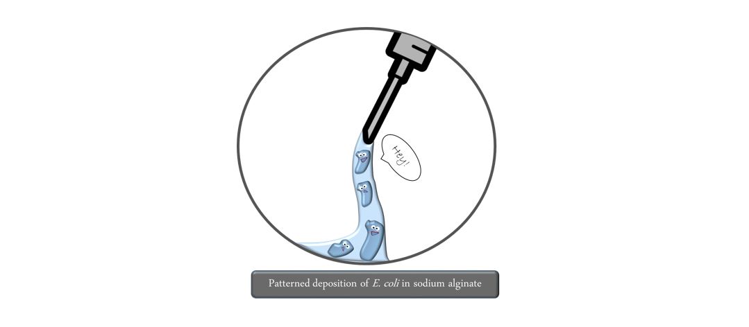
Biolinker
From a 3D printer to a Biological System
Overview
The Biolinker - a DIY biofilm printer
We built a functional prototype of a 3D printer, our Biolinker, from cheap DIY open source parts, which is capable of bioprinting bacteria in shapes based on lines and circles. The bioink is made out of our engineered bacterial cells, which we successfully immobilized into an alginate hydrogel. With this bioink we can print lines with a resolution (thickness) of down to 1 mm. We were able to successfully print and image of up to 4 layers of bioink with only little mixing between the layers. Our prototype passed its final test in a collaboration with the iGEM team from Groningen confirming that it can not only be easily used by any other iGEM team, but also is even compatible with the different strain they were using, B.subtilis. Although redissolving jellified alginate becomes more challenging with size, our bacterial cells were able to survive under alginate dissolving conditions for 36 hours.


Accomplishments
- Build a functional prototype of a DIY 3D bioprinter and characterize it
- Collaborate with another iGEM team using our prototype
- Create an instructional video, handbook manual and a bill of materials
- Microscopical characterization of layers containing different bacteria
- Integration with modeling
Introduction
Since the 1980s numerous applications and materials have been developed for 3D printing. Nowadays, starting from a computer generated three dimensional image file (stereolithography .STL) metals, plastics or even food can be printed in any shape imaginable. Recently, significant progress has been made in the three dimensional printing of mammalian stem cells towards creating artificial organs within many renowned research groups all around the world working in the field. Since 3D bioprinting has high potential and is still largely unexplored, we set out to find a novel application. Inspired by machine-specific properties: precision and reproducibility, we came up with the idea to print cells in a structurally defined pattern. In this way we intend to meet the increasing demand of reliable product testing in medicine and health applications.
In the following pages, we describe the development and the printing conditions of our prototype.
Making 3D Biofilms
Biolinker: From 3D printer to a Biological System
Normal 3D printers generally follow the same principle: a raw material is transferred into liquid state by melting, or utilization of a fine powder, to obtain high precision upon deposition of the material. At this point the material needs to form a stable, solid structure,by cooling it, or using UV light that chemically solidifies the compound.
Based on 3D printer general principles, we identified the following design requirements for the Biolinker:
- Liquid bioink
- Curing reaction to form a supporting scaffold
- Removable scaffold to obtain the final bacterial structure
- Cells need to survive every step of the entire process
- Sterile environment needs to be maintained at all time
From these points, we came up with a six step process to make a 3D biofilm!
How we print bacteria in 3D
Step 1: The first step already determines the outcome printing quality. The bioink needs to be deposited at the exact right spot to print a structure with high precision. Firstly, this depends on the precision of the motors moving the printhead across the stage. Secondly, it depends on the bioink itself. Its viscosity, flow rate and surface tension. Finally, the adhesive properties of the surface (in the following referred to as biopaper) upon which the material is deposited determine the outcome.

Step 2: By pretreating the biopaper with calcium chloride, the bioink is immediately exposed to free calcium ions upon deposition. This triggers the crosslinking of the alginate polymer to afford a stable gel. You can imagine this like spaghetti before and after boiling them. This step needs to take place as fast as possible to avoid liquid movements leading to unwanted losses in precision. Here it is important to ensure that both the liquid and gel form of alginate do not pose any harm to bacterial cells and that they are sustained with water and nutrients.
Step 3: Our cells are now trapped in a tangle of spaghetti. It’s time to start what they were made for: connect! Rhamnose induces the production of protein units CsgA which are exported out of the cell and self-assemble to form nanowires which connect the bacteria.


Step 4: Protein production and diffusion at the right place takes time. To create a strong interaction between cells, this step takes up to 24 hours. However, placing the biofilm into a 37 degrees incubator leads to the alginate gel drying out and eventually cell death. To prevent this, storage at room temperature was found as compromise.
Step 5: Now that a stable connection between cells has been established it is time to liberate the final product. To do so, the spaghetti tangle around the biofilm needs to go. Sodium citrate is used to complex the bridging calcium ions which then are replaced with sodium ions. Like this, the alginate is stepwise dissolved and can finally be washed away.


Step 6: But did it work? Let’s find it out by looking at the biofilm under the microscope. Certain dyes specifically interact with the bacterial nanowires created by our bacteria. These are known as a Congo Red or a Crystal Violet assay. In this manner, we can distinguish, whether the nanowires and thus our biofilm has been formed.

The Biolinker
The story of our DIY 3D Printer. From commercial 3D Printers, to modified inkjet printer to K'NEX toys.
Initial 3D Printer ideas
Our project started with the idea to develop structured biofilm formation. The most effective solution would be a retail 3D bioprinter, so we first thought to buy a 3D Printer. However the solution was not viable. For one, a retail 3D printer is expensive. Second, in a normal 3D printer, the printhead is heated, resulting in the death of our bacteria. Third, our proposed bioink has a different viscosity than the one used in 3D printers. Finally, for printing a continuous line, we need to adapt the printing speed which is hard to do with existing 3D printers. In conclusion, our research told us a commercial 3d printer was not optimal, so we started looking for other ideas.
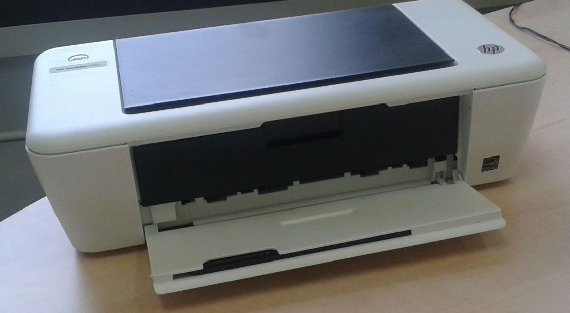
After a thorough search on the internet, we found a lot of manuals to transform an inkjet printer into a 3D printer. Most of the inkjet printers use a piezoelectric Drop-on-Demand method. This method is based on spitting out the ink by using very small electric shocks, which our bacteria could survive. Another advantage of the inkjet printer over a commercial 3d printer is that is it much cheaper! We decided to buy such a printer, but then, problems arose. For example, the printer is impossible to reprogram by connecting it directly to a computer, as its software is embedded into the printer circuitry.
First version of K'NEX printer
A 3D printer is actually nothing else than a machine that can move in three directions and has something that extrudes the ink.
After a visit to the company Ultimaker (see: Report) we were inspired by the experts working there. This advice drove us to think about a simpler, more efficient idea. We thought to build our own printer with a toy construction set: The K’NEX. Thus, we started building a 3D printer that fits our needs. By forming a structure from rods and linkers, and connecting them to gears, motors and some transmission chains, we finished our first version. The mechanism could print circular shapes, holding a needle fixed while moving the platform on which the ink was extruded.
In order to let the bacteria ink come out of the needle, the K’NEX printer was coupled to a syringe pump. The syringe pump is able to extrude the bacteria ink with an adjustable speed. The adjustability of the speed proved to be essential: if the extrusion speed is too high, the printed line becomes non-continuous. If the printing speed is too low, the printed line becomes too broad. Our challenge is therefore to make the perfect combination of the speed of the printhead with the speed of the syringe pump to get an optimal printing result.
Biolinker - Specifications
This first printer version was good for initial testing, but of course our goal is to make a printer which can print in all three dimensions! We therefore started building our K’NEX printer 2.0, also known as the BIOLINKER. For this version, we required a considerable amount of K’NEX pieces. But instead of buying them, we were lucky enough to find many enthusiasts that were willing to donate their toys for Science!
We started building the X and Y dimensions. By utilizing motors to rotate a gear mechanism that drives a belt for X and Y axes individually, we could move the printing needle in either of these dimensions. Afterwards, we added the Z axis by using a similar gear mechanism to move the platform on which extrusion is done. Moreover, each axis movement has two speed settings characterized further down in the page. We added this by switching the transmission on either a larger or a smaller gear, much like the mechanism found in a bike. Our final design was finished!
After testing and optimizing this design, we decided that it is good enough to make it our final version! You can see in fast forward how the printer can be built in less than one hour, if all steps are known and pieces available.
So we had our prototype, but was it any good? In order to find that out, we contacted the iGEM team from Groningen (NL) and asked for their help. They agreed to test our methodology of 3D printing bacteria by using our Biolinker prototype and even took it one step further by using a different bacterial strain, B.Subtilis. They succeeded at using our prototype and our methodology was also compatible with their strain. You can find the extensive report of our collaboration here.
Characterization
1. Characterization of movement in xyz

Our printer is like a bike equipped with two different gear wheels to enable changes of the printing velocity. Using a camera, we recorded nine runs of the printhead along a ruler. Using this video data, the distance covered in time steps of 1.0 seconds was measured. The average distance covered in 11 seconds was 6.57 cm.

After changing the gear, the same experiment was conducted now at a lower tip velocity. Here, the average distance covered in 16 seconds amounted to 3.44 cm.

From these data, the velocity during each time interval was calculated and the velocity distribution was plotted in the following graph. The average velocity of the fast gear wheel was 0.6 cm/second.

For the slow gear wheel, we found an average velocity of 0.21 cm/second which is approximately ⅓ of the velocity achieved by the larger wheel. From the graph we can observe that the velocity is 0.2±0.1 cm/second.

While the fast gear wheel prints with a velocity distribution of roughly 0.6±0.2 cm/second, the slow gear wheel prints at roughly 0.2±0.1 cm/second. Thus, to cover a fixed distance of for instance 0.6 cm, both gear wheels print with the same precision: 0.6±0.2 cm. However, practical experience showed control of the printhead movement and ink flow rate fine tuning to be easier with the slow gear wheel.
In order to characterise the movement in the z-direction, a similar experiment was conducted: movement of the printer surface along a ruler was recorded with a video camera. Due to the reduced velocity in z-direction, intervals of 3 seconds were chosen this time. The experiment was repeated five times and the average distance covered is presented in the following graph:

The sigmoidal shape of distance covered by the stage is explained by the arm moving the stage being fixed to a wheel. When turning, the increase in z-direction is very little, reaches a maximum after 90° of rotation and then decreases again.
2. Characterisation of the alginate line thickness

In order to be a real 3D printer following the principle of stereolithography, many layers need to be deposited on top of each other to generate the aspired structure. But can we print several layers on top of each other without great losses in precision, thus: how thick will the lines be? To answer this question, we printed lines of one, two and three layers in triplicate using our Biolinker and measured their thickness using a microscope (10x).

Adding a second layer of alginate on top of the first layer lead to an average increase of line thickness of 7%. The addition of two layers increased the line thickness by 21% compared to a single layer.
With this, we have proven that we can print several layers of alginate on top of each other without significant losses in resolution during this process. The next question thus is: how do the layers look on the inside? Do they mix or do they form clean interfaces in between them? To answer these questions, we conducted the following experiment: two types of bioink were prepared containing each either GFP or RFP expressing bacterial cells. These two types of bioink were used to manually create two alternate layers of radial biofilms on a plasma cleaned coverslip: the bottom layer contained RFP expressing cells with a layer of cells expressing GFP on top of it. In order to analyse our layered biofilm, we used a spinning disk microscope. Imaging was done by starting at the lower end of the first layer and increasing in steps of 2 micrometer over a distance of 146 micrometers. Each layer was imaged both at 488 nm and 561 nm and the final image was obtained as an overlay of both images. This data set was used to create a 3D projection, showing that the bottom layer is approximately 29 micrometer in height and contains only cells producing RFP. The layer on top is approximately 34 micrometers in height and contains only cells producing GFP. Mixing between the layers is almost negligible, proving that the hydrogel assists in layer formation and the system is useful in printing the biofilm.
The extensive protocol can be found here.

With this image we were able to show that we can deposit two layers in a controlled way on top of each other. The area with low cell density and mixed GFP/RFP is limited to a thickness of <10 μm.
3. The syringe pump
Depending on the volume and supplier of your syringe of choice, the inner diameter varies strongly. This however is an important input parameter for the syringe pump to control the rate of bioink extrusion to a constant flow rate. The inner diameter usually can be found on the supplier’s webpage. We found a flow rate of 100 µL/min to be a good value to start experiments. Minor adjustments might be necessary depending on the exact velocity at which the tip moves across the biopaper. For our experiments, we were using a Harvard Apparatus ‘11’ Plus (70-2208) syringe pump.

Design and Integration
Engineering bacteria to form a patterned biofilm
Setting out with barely more than the idea of connecting cells to form a patterned biofilm, we had to think about how to engineer our bacteria to reach this goal in the most efficient way. As the first step, we started to think about possible designs of our biobricks.
Clearly, since CsgA is the protein monomer for amyloid nanowires, this gene will be on our plasmid. But which promoter to use? Inducible or constitutive? A constitutive production of the protein monomers would lead to a premature formation of nanowires which could eventually lead to clumps clogging the tubes and leading to losses in precision. For this reason, we chose an inducible Rhamnose promoter. However, coming to this realization we concluded that we also need a CsgA knockout strain to conduct our experiments with. Finally, for an efficient optical assay of our biofilm product we decided to incorporate fluorescence in the form of GFP or RFP inside of our cells.

However, next to the protein creating the nanowires, many others exist which are important: CsgB is a membrane protein which functions as the anchor on the cell and triggers the aggregation process of CsgA to a nanowire. Presumably, depending on the level of expression of these membrane proteins we can influence the amount of connections per cell. In this manner, we imagined to manipulate biofilm strengths according to the situation at hand. In order to investigate this effect, we designed the biobrick containing CsgB with a constitutive Anderson promoter of low, medium and high inducer strength. Since we wanted to investigate the interactions between CsgA and different levels of CsgB, we designed this biobrick in the pSB4K5 backbone to avoid problems with incompatibility groups. The proteins CsgC, CsgE, CsgF and CsgG are involved in the maturation, correct folding and export of CsgA. For this reason we imagined overexpression of these proteins to have a positive effect on the total extracellular amount of available, functional CsgA. By increasing this amount, we hoped to increase the rate of biofilm formation.

Using amyloid nanowires to connect the cells, the question arises how long these nanowires can grow. Unfortunately, no exact number can be assigned to usual length of these nanowires. While their thickness has been characterized to be 100 to 350 nm, their length is of several micrometers (Pitkänen, M., et al., 2010). From this data, we created a model using the measures of a bacterial cell and different cell densities (OD600) to calculate the mean distance between each cell either head on or sideways (since E.coli has a worm-like appearance) assuming homogeneous orientation. From this, different required cell densities can be derived depending on the level of crosslinking desired. Two cutoff lines of 10 µm and 5 µm distance are plotted for easy orientation.

Corresponding to this, molecular sizes of the CsgA protein monomer were used to calculate the amount of protein monomers required for connecting two cells at a certain density. This can be used as an orientation for the time it takes to crosslink two cells assuming constant protein production and no differences by diffusion.

DIY Manuals
Build your own Biolinker and prepare all necessary materials and solutions for printing
In this section we will show you how easy and fast it is to build your own Biolinker from toy sets. We prepared a manual that everyone can use as a guideline to build a 3D printer at home. Next, we detail how you can prepare all the necessary materials and solutions before starting to print. Finally it all comes together in a video highlighting all important steps in the printing process. To make things even more easy we detail a bill of all the materials necessary to make your own 3D printed biofilm.
Build your own Biolinker
Navigate through our manual by either clicking right/left buttons, or by turning the page from the corners. You can also download a pdf version here. Biolinker Building Manual
Preparing materials and solutions
1. 100 mL of sodium alginate stock for bioink
Stirr 1 g of sodium alginate in 100 mL of sterile Milli-Q in an autoclaved 400 mL bottle over 5 hours at 50 degrees Celsius until a homogeneous, white mixture is obtained. Place the bottle into a microwave and pasteurized by heating to boiling point for 30 seconds at 800W. Cool it down to room temperature quickly by using a water bath. Add the corresponding antibiotic required for your specific cells in the appropriate amount and keep the bioink in the fridge until usage.
Grow your cells overnight in LB+antibiotic. If you intend to connect the cells with CsgA nanowires: please look at our model here to identify the required OD600 of your bioink.
To print without crosslinking: Spin down the cells of a 5 mL bacterial over night culture, resuspend the pellet in 100 µL of sterile LB and mix with 900 µL of previously prepared pasteurized sodium alginate by pipetting up and down and final vortexing.
1 mL of bioink can be used to print medium sized patterns on three agar plates.
Note: the solutions 2,3,4 need to be autoclaved, this can be done together
2. Sterile CaCl2 (0.1M)
Dissolve 1.11 g of calcium chloride (anhydrous) or 1.47 g (dihydrate) in 100 mL Milli-Q and autoclave the obtained solution.
3. Sterile sodium citrate (0.1M)
Dissolve 2.14 g of sodium citrate (monobasic) or 2.94 g sodium citrate dihydrate in 100 mL Milli-Q and autoclave the obtained solution.
4. LB agar plates as print surface
Dissolve 14.24 g LB agar (obtained from Sigma Aldrich) in 400 mL Milli-Q water. Autoclave.
Reheat the autoclaved LB agar in the microwave carefully until boiling point, cool down until you can hold it with your hands and add the antibiotic matching the resistance of your cells in the required amount. Make plates under sterile conditions using roughly 10 to 20 mL. Store them in the fridge upside down until usage.
Before printing, plate 500 µL of calcium chloride (0.1M) on the LB agar plate using standard plating technique to enable formation of a hydrogel. If further cell growth is desired, keep the plates at room temperature. At 37 degrees the alginate dries out within 24 hours.
Video Tutorial
Bill of Materials

Protocols
The digitalized protocols can be found in the Notebook page.
Experimental approach on how to 3D print bacteria

When we started our first experiments on 3D printing bacteria, it became quite obvious we would need something to support our cells:
Printing RFP expressing cells in LB medium in the shape of a circle worked, but gravity and surface properties were working against us making the line almost 1 cm thick.
Sodium alginate is commonly used in biology to create a hydrogel by using calcium chloride and can be redissolved again by complexing the calcium ions and replacing them again with sodium ions. This hydrogel is both viscous enough to be immobile, while at the same time provides optimal living conditions for the bacteria.
Therefore we decided to disperse our bacteria in a solution of sodium alginate which would form a stable hydrogel during the printing process.
Our initial idea was to simultaneously extrude the bioink containing sodium alginate and the bacterial cells from one needle and the calcium chloride solution from another needle which is in direct contact with the first one. The idea was to directly jellify the alginate when leaving the needle, thus creating a cylinder with a thickness of the needle’s inner diameter. However, at low flow rates droplet and thus bead formation was unavoidable and high flow rates resulted only in dissatisfactory results (low control).

Since the mechanical setup additionally posed some difficulties, we tried a different approach: direct extrusion of the sodium alginate solution into a larger volume of dissolved calcium chloride. The flaws of this setup quickly became obvious: instead of extruding a cylinder, the hydrogel was mostly sticking to the needle and clogging was inevitable at low flow rates. Finally, the hydrogel was floating around freely in the liquid thus the required spatial precision for 3D printing was impossible to achieve in such a setup.
We concluded that we would need something to which the hydrogel could attach, something that would keep bacterial cells alive and in the best case could also be used as a calcium ion source for the gel formation. We found such a material in LB agar to which we added calcium chloride at a concentration of 0.1M.
This turned out to be quite successful: diffusion of calcium ions from the agar was able to trigger the hydrogel formation even through a thickness of eight layers printed successively on top of each other. However, we identified one major flaw: in order to redissolve the hydrogel, the calcium ions are complexed with sodium citrate and replaced with sodium ions. Introducing an excessive abundance of calcium into the agar would thus lead to problems at a later stage when trying to redissolve the alginate.

4.6 cm in diameter
1.5 mm single line thickness
3 mm final line thickness (8 layers).
For this reason, we adapted the system in the following way: we plated 500 µL of 0.1M calcium chloride solution directly before the printing. In this manner, the top layer of the gel was sufficiently saturated with calcium ions to produce the hydrogel, but calcium ion abundance was kept as little as possible.
The distance between the tip and the print surface is of great importance. Initial experiments with larger distances were optically characterised by resembling a pearl necklace: due to the large distance, droplets were able to form in a repetitive pattern disturbing the straight line. In order to prevent this, the distance between the tip and the print surface thus must be kept as little as possible. However, due to unevenness of the surface, this lead to some problems. Being close to the agar, the needle often got stuck in the surface due to the nature of the mechanical movement. To tackle this problem, we decided to change our setup from extruding the alginate through a needle to leaving out the needle and only using the tubing. This offered the advantage of a simpler setup and improved flexibility when the tip touched the print surface.
This setup has proven to meet our purposes well and was used by us until the end.
Finally, we are working with bacteria, so what about sterility? To ensure high quality in our experiments, all our solutions were autoclaved to prevent unwanted contamination. Unfortunately, sodium alginate is decomposed during autoclaving. For this reason, we decided to use a trick that is more than a hundred years old: pasteurisation! The alginate solution was rapidly heated to its boiling point using a microwave and then immediately cooled down using a water bath. Like this, the amount of microorganisms was reduced while maintaining the alginate functional. Finally, antibiotics were added to all our samples to kill all bacteria which do not contain our antibiotic resistance.
Sterility during the printing process can be maintained by setup in a laminar flow cabinet:

Dissolving the alginate
Although dissolving hydrogel beads is described in literature as straightforward (J.A.Rowley et al., 1999), we experienced problems with dissolving our hydrogel samples to obtain the biofilm only product after 3D printing. In literature, the addition of 10 mL 2% (w/v) sodium citrate is described as sufficient to completely dissolve the hydrogel within 20-30 minutes. Unfortunately it turns out this does not hold true for larger hydrogel fragments as we were experimenting with, but works only efficiently on a very small scale ( < 400 µm).
Trying to regain the in the hydrogel entrapped cells, we incubated 100 µL of hydrogel bioink containing cells constitutively expressing RFP in 1 mL of 2% (w/v) sodium citrate at 37°C for 36 hours. While we were able to show that the cells did survive this procedure by inoculating them in fresh LB and regrowing dark red cells, the hydrogel however had to our big disappointment barely dissolved.
Trying to force its dissolution, we incubated 100 µL of hydrogel in 1 mL of 2% (w/v) sodium citrate at 50°C, 300 rpm over 48 hours. To our large disappointment, not even these conditions were capable of dissolving the hydrogel.
Repetition of the above experiments with low concentration sodium alginate (1% w/v instead of 2%) lead to the exact same results.
To this point, we have not been able to entirely dissolve and remove the supporting alginate hydrogel. In the future, more effort will have to be put either into developing and optimizing conditions capable of both fully dissolving the hydrogel and keeping the cells alive, or reorientation towards a different compound that can be used as a stabilising scaffold for the bacterial cells in the printing process.
References
Pitkänen, M., et al. "Nanofibrillar cellulose—in vitro study of cytotoxic and genotoxic properties." Proceedings of the International Conference on Nanotechnology for the Forest Products Industry Otaniemi. Espoo, Finland. 2010.
J. A. Rowley et al. “Alginate hydrogels as synthetic extracellular matrix materials.” Biomaterials, 20, 1999, 45-53.
W. C. Wilson, T. Boland, Cell and Organ Printing 1: Protein and Cell Printers, The Anatomical Record, 2003, 272A, 491-496.
S. Khalil, W. Sun, Biopolymer deposition for freeform fabrication of hydrogel tissue constructs, Materials Science and Engineering, 2007, C27, 469-478.
S. Murphy, A. Atala, 3D bioprinting of tissues and organs, Nature Biotechnology, 2014, 32, 8, 773-785.
R. Mapi, S. Chaitidou, F. Trikka, D. Kyriakidis, Encapsulated Escherichia coli in alginate beads capable of secreting a heterologous pectin lyase, Microbial Cell Factories, 2005, 4, 35.
W. R. Gombotz, S. F. Wee, Protein release from alginate matrices, Advanced Drug Delivery Reviews, 1998, 31, 267-285.
V. Mironov, R. P. Visconti, V. Kasyanov, G. Forgas, C. J. Drake, R. R. Markwald, Organ Printing: Tissue spheroids as building blocks, Biomaterials, 2009, 30, 2164-274.
T. Boland, T Xu, B. Damon, X. Cui, Application of inkjet printing to tissue engineering, Biotechnology Journal, 2006, 1, 910-917.