Difference between revisions of "Team:EPF Lausanne/Project/Description"
| Line 49: | Line 49: | ||
</div> | </div> | ||
<div class="col-md-4"> | <div class="col-md-4"> | ||
| − | <img src="https://static.igem.org/mediawiki/2015/f/fe/Dcas9.png" alt="dCas9 fused to a RNAP recruiting element" style="width: | + | <img src="https://static.igem.org/mediawiki/2015/f/fe/Dcas9.png" alt="dCas9 fused to a RNAP recruiting element" style="width:80%"> |
</div> | </div> | ||
</div> | </div> | ||
| Line 59: | Line 59: | ||
</div> | </div> | ||
<div class="col-md-4"> | <div class="col-md-4"> | ||
| − | <img src="https://static.igem.org/mediawiki/2015/f/f0/Dcas9%2B.png" alt="dCas9-TF activating" style="width: | + | <img src="https://static.igem.org/mediawiki/2015/f/f0/Dcas9%2B.png" alt="dCas9-TF activating" style="width:80%"> |
| − | <img src="https://static.igem.org/mediawiki/2015/0/08/Dcas9-.png" alt="dCas9-TF inhibiting" style="width: | + | <img src="https://static.igem.org/mediawiki/2015/0/08/Dcas9-.png" alt="dCas9-TF inhibiting" style="width:80%"> |
</div> | </div> | ||
</div> | </div> | ||
| Line 70: | Line 70: | ||
</div> | </div> | ||
<div class="col-md-4"> | <div class="col-md-4"> | ||
| − | <img src="https://static.igem.org/mediawiki/2015/8/81/Dcas9_and_sgRNAs.png" alt="dCas9-TF and sgRNAs" style=" | + | <img src="https://static.igem.org/mediawiki/2015/8/81/Dcas9_and_sgRNAs.png" alt="dCas9-TF and sgRNAs" style="width:80%"> |
| − | <img src="https://static.igem.org/mediawiki/2015/5/5b/Dcas9_bound.png" alt="dCas9-FT bound" style=" | + | <img src="https://static.igem.org/mediawiki/2015/5/5b/Dcas9_bound.png" alt="dCas9-FT bound" style="width:80%"> |
</div> | </div> | ||
</div> | </div> | ||
Revision as of 00:40, 17 September 2015
Bio LOGIC in 12 questions
What does Bio LOGIC stand for?
It stands for "Bio Logic Orthogonal gRNA-Implemented Circuit”. In a few words, we are working on implementing digital-like circuits in cells using dCas9.
Don’t biological circuits already exist?
Yes. However, difficulties in the multiplication and chaining of logic elements has hindered the complexification of these circuits. To overcome these limitations, an ideal in vivo logic element should be modular, reusable and orthogonal - i.e avoiding cross-talk with its host organism and the other elements of the circuit.
So, what’s different about your system?
We can avoid some of these issues by making a completely synthetic biological circuit. This is what we are doing by using the newly discovered dCas9 as a synthetic transcription factor.
How can dCas9 be used as a transcription factor?
Well, you know CRISPR-Cas9, the RNA-guided DNA endonuclease, right? We are using dCas9, the catalytically dead version of Cas9, which lacks the ability to cleave DNA. We will fuse dCas9 to a RNA Polymerase (RNAP) recruiting element. Depending on where it binds, this complex will either activate or inhibit transcription.

How does this activation/inhibition system work?
When dCas9 binds at an optimal distance upstream from the promoter, the RNAP recruiting elements with which it is fused will, in fact, recruit RNAP, thus activating the transcription of the gene that is controlled by this promoter. However, when dCas9 binds on the promoter, it will sterically hinder RNAP from binding at the transcription start site, thus inhibiting the transcription of the gene.


How do you guide the dCas9 to activating/inhibiting region?
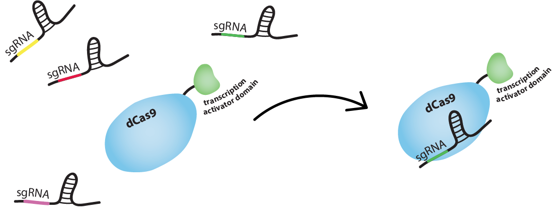
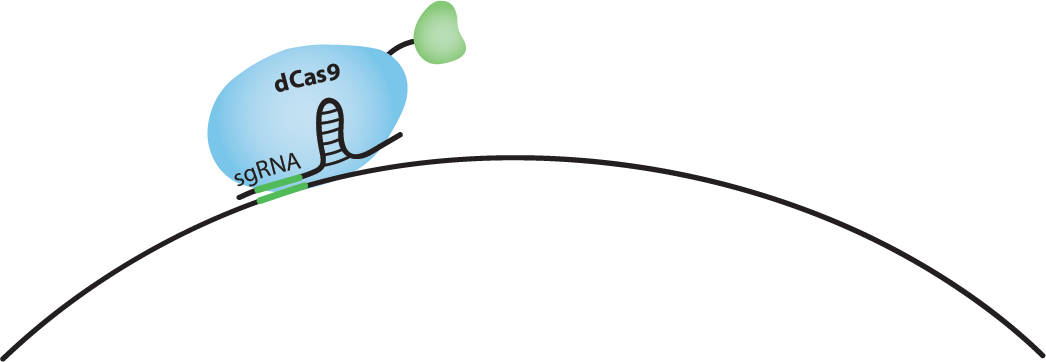
dCas9 works just like Cas9, meaning it is RNA-guided. Guide RNA (gRNA) and dCas9 can form a complex. This complex will bind tightly to a DNA sequence which is complementary to the gRNA. So we can guide dCas9 to activating or inhibiting regions of a promoter by producing gRNAs complementary to these sequences.


Can a gRNA-dCas9 complex activate one region and inhibit another in the same cell?
Yes, a gRNA-dCas9 complex will bind to any sequence that is complementary to the gRNA. So, if the activating region and the inhibiting region of different promoters have the same sequence, two identical gRNA-dCas9 complexes can bind both at the same time. This is also why we have to be careful not to target regions that are present in the genome of the host organism, to not interfere with cell’s standard function.
What happens if the activating region and the inhibiting region of the same promoter are bound by dCas9 at the same time?
That is a very good question! It was shown that inhibition is dominant in yeast (S. cerevisiae) [1]. This means that, if both activating and inhibiting regions are bound, the transcription of the gene will be inhibited. One goal of our project is to find out if this is also the case in bacteria (E. coli). We will also test our system in yeast.
How are you going to use this to make biological circuits?
Because of time constraints, we won’t be able to make a real biologic circuit. We aim to make and characterize a biological equivalent to the simplest element in a digital circuit, a transistor. Transistors function like switches for electric current. Our bio-transistors work like switches for the transcription of a gene and can be assembled to form biological circuits.
What does your bio-transistor look like?
The bio-transistor is simply a gene with a promoter. We insert this synthetic sequence in a cell, along with a gene producing dCas9 fused to the RNAP recruiting element and the sequence that produces an gRNA complementary to either the activating or the inhibiting region of the promoter. dCas9 and the gRNA are produced, they form a complex which binds to the activating or inhibiting region of the promoter, thus “turning the gene on or off”.
How do you make biological circuits from bio-transistors?
Well, digital circuits are made out of logic gates, elements that perform basic logic functions (AND, OR, NOT, NOR, NAND, XOR, etc.), and logic gates are made out of transistors. Our idea is to assemble our bio-transistors into logic gates. By linking the output of one logic gate to the input of another one, we can make biological circuits that function in the same way as a digital circuit.
Sounds cool! But what can this be used for?
A single transistor is not very useful. However, by assembling a certain number of bio-transistors, we could make complex biological circuits that would have different outputs depending on many inputs. For example, we could make complex biosensors by building a circuit that is activated by the presence of a specific combination of molecules, or that has a different response for different combinations of molecules. This is only one example among the many applications of biological circuits.
Find out more about how we implemented our system in E. coli and in S. cerevisiae or about what’s already been done with biological circuits and the publications that inspired us, or check out our results.
References
[1] Tunable and multifunctional eukaryotic transcription factors based on CRISPR/Cas, F. Farzadfard, S. D. Perli, T. K. Lu
Design in E. Coli
The synthetic transcription factor: dCas9-w
We will use the DNA-binding activity of the catalytically 'dead' version of Cas9, dCas9, to regulate genes. Thus, we will use dCas9 as a transcription factor.
For activation to be possible, dCas9 needs to be fused to a RNA polymerase (RNAP) recruiting element. We fused the w (omega) subunit of RNAP to dCas9 [1]. The w subunit works as a RNAP recruiting element in E. coli when working in a strain in which RNAP lacks the w subunit. We used JEN202, "an E. coli MG1655 mutant in which rpoZ, encoding for the w subunit of RNAP, was replaced by a spectinomycin resistance gene" [1], for all fluorescence measurements.
We used single guide RNAs (sgRNA) to guide dCas9-w to targetted regions. An sgRNA "comprises a complementary domain that binds to the DNA followed by a “handle” that is bound by dCas9" [3]: in our case dCas9-w. dCas9-w and an sgRNA form a complex which will tightly bind a DNA sequence complementary to the 'complementary domain' of the sgRNA.
Find out how we regulate genes with dCas9-w in the next section!
The bio-transistor
The bio-transistor for E. coli consists of a gene controlled by a synthetic promoter.
We synthesized promoters based on the constituve promoter J23117 [1]. This promoter consists of BBa_J233117, preceded by a protospacer-adjacent motif (PAM) rich upstream regulating sequence (URS).
We tested our system for the promoter J23117 and J23117alt. The sequence for J23117alt was randomely generated, except for the -35 and -10 regions that we conserved. Some of our team members wrote a program in C++ and then in Python that generated a random sequence that conserved part of an original sequence. To observe the activity of a single bio-transistor, we used a gene encoding for green fluorescent protein (GFP) as a reporter gene.
If dCas9-w guided by an sgRNA binds on the promoter close to the transcription start site, the binding of RNAP to DNA is sterically inhibited, and transcription is repressed. We chose to use sgRNAs complementary to sequences 14 or 18 bp upstream from the transcription start site (TSS). If dCas9-w guided by an sgRNA binds at an optimal distance upstream from the promoter, the w subunit recruits RNAP and transcription is activated. We chose to use sgRNAs complementary to the sequence 71 bp upstream from the TSS. [1]If both the inhibiting and the activating sgRNA for the same promoter are present in the same cell, we foresaw 2 possible situations. We simulated both with our model: either dCas9-w can bind both the activating and the inhibiting sites, in this case the model predicts that the inhibitory will tend to be stronger, or dCas9-w cannot bind both sites due to sterical hindrance in which case the overal effect should tend to be activating. For more information on these situations, check out our Modeling page, or see how this turned out experimentally in our Results!
We constructed plasmid pdCas9-w, encoding for dCas9-w controlled by a Tetracylcine-inducible promoter, from pdCas9-bacteria [2] and pWJ66 [1]. We synthesized 'sgRNA expressing cassettes' (IDT) controlled by a constitutive promoter and inserted these into pdCas9-w. We inserted either one sgRNA (activating or inhibiting) or two sgRNA (1 activating and 1 inhibiting, or 2 inhibiting, affecting the same promoter). We used pWJ89, GFP controlled by the J23117 promoter, [1] as the first 'reporter-transistor'. We constructed pWJ89alt, GFP controlled by the J23117alt promoter, as our second 'reporter-transistor'.
We transformed JEN202 cells with one of the 'reporter-transistors' and pdCas9-w with sgRNAs complementary to the activating and/or inhibiting regions of the promoter of the transistor, and measured the fluorescence of these cells with a plate reader or by flow cytometry. See the results here.
References
[1] Bikard, D., Jiang, W., Samai, P., Hochschild, A., Zhang, F., & Marraffini, L. A. (2013). Programmable repression and activation of bacterial gene expression using an engineered CRISPR-Cas system. Nucleic acids research, 41(15), 7429-7437.[2] Qi, L. S., Larson, M. H., Gilbert, L. A., Doudna, J. A., Weissman, J. S., Arkin, A. P., & Lim, W. A. (2013). Repurposing CRISPR as an RNA-guided platform for sequence-specific control of gene expression. Cell, 152(5), 1173-1183.[3] Alec AK Nielsen & Christopher A Voigt (2014). Multi-input CRISPR/Cas circuits that interface host regulatory network. Molecular systems biology, 10(11), 763.


