Team:Czech Republic/Modeling
Modeling
Contents
Abstract
IOD systems function at both the intracellular and intercellular level. Intracellular biochemical reactions determine signalling activities and gene expression. Extracellular reactions include signalling molecule diffusion and cell movement with cell-cell interactions. At each level models of various complexity are available. We selected minimalistic models that capture only the key design elements and integrated these models in a single simulator CeCe. Subsequently simulation was used to study the robustness and efficiency of different signal transmission patters in identifying cells with specific marker profiles while minimising false positives.
Key Achievements
- Developed a simulation environment CeCe to capture the complexity of cell-cell signal transmission.
- Designed an IOD chemical reaction network model.
- Developed a schematic architecture for conceptual modelling of signal transmission networks.
- Designed a two IOD signal transmission network suitable for the IOD band.
- Illustrated the robustness and efficiency of the IOD band design in CeCe simulations.
Methods and Software
IOD biochemical reactions
Intracellular reactions are modelled as stochastic biochemical reactions. Biochemical reactions were simulated using Gillespie's next reaction method. To correctly model the multicellular nature of the system, well-mixed assumptions are only applied at the individual cell level. In other words, each cell was treated separately in evaluating propensities and executing reactions.
Systems comprising of many cells and many molecular species extend the computational time making longer simulations impractical. Hence, to keep the number of molecular species to a minimum, boolean approximations were used to represent gene activities and signalling pathway activities.
The following simple chemical reaction network was used in the simulation analysis below. The system comprises the following molecular species:
- \(phe_i\): extracellular phermone signals, \(i = 1,2,...\)
- TF: local transcription factors (note, there is no need to index the transcription factors as they are always local to the associated IOD)
- \(tag_i\): surface locational tag, \(i = 1,2,...\).
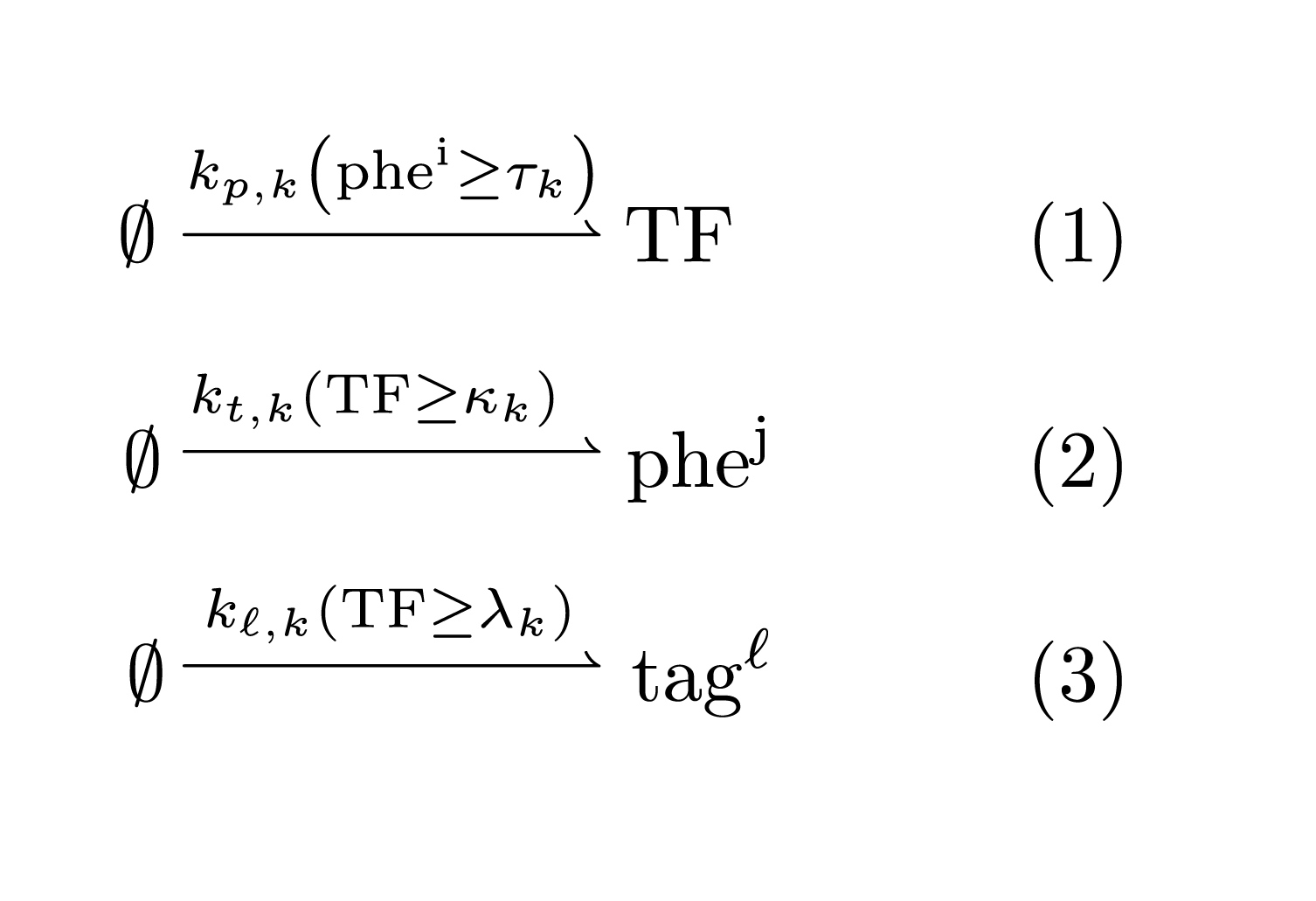
An IOD \(k\) is then described by the following chemical reaction network:
Above, the reaction rates include boolean function. For instance, the expression \(r = k_{p,k} (phe^i \geq \tau_k)\) should be interpreted as the step function \[ r = k_{p,k}, \text{ if } phe^i \geq \tau_k, \text{ and }0\text{ otherwise.} \] Hence, an IOD is associated with six parameters:
- \(k_{p,k}\): the activation rate of the transcription factor TF
- \(k_{t,k}\): the production rate of the output pherome factor
- \(k_{\ell,k}\): the production rate of the locational tag.
- \(\tau_k\): the TF activation threshold from the input singal
- \(\kappa_k\): the pheromone production activation threshold from the TF
- \(\lambda_k\): the locational tag activation threshold from the TF
This represents the template of IOD system chemical reaction network. An actual IOD system may have multiple tags or output pheromones. It is also clear how this model could be extended to accommodate other local species determining the decision making logic.
Signal transmission networks
IOD systems can be tuned at many levels: intracellular signal transduction, genetic regulation, signal production, and intercellular signal transmission including cell-cel interaction. We found no intuitive schematic architecture allowing intuitive comparison of the fundamental design differences. Through several iterations within the project, the following signal transmission network (STN) schematic proved to be most useful.
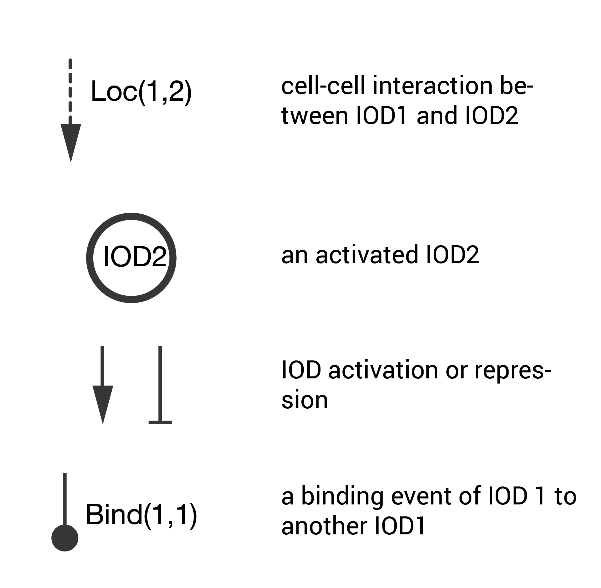
The schematic key is pictured below. These are the important points of this abstraction tool.
- Cell-cell interactions that lead to an activation are treated as signals denoted by dashed line (other cell-cell interactions are not shown).
- For an activating cell-cell interaction, the activated cells are denoted by named circles (cells that are not activated are not shown).
- Mutual activation/repression between interacting cells is denoted by sharp or blunt arrows (this follows the genetic regulatory network nomenclature).
- Binding initiated by surface location tags is denoted by a round arrow.
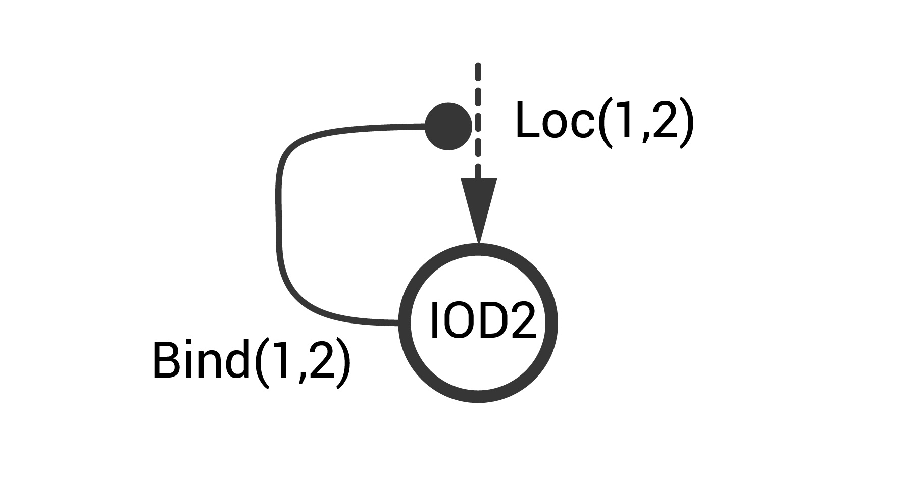
Consider an STN example that represents the positive autoregulatory motif at the cell-cell level. This system includes two IODs (IOD1 and IOD2). IOD1 constitutively produces a location tag (\(tag^1\)) and a pheromone signal \(phe^1\) that is detected by IOD2. Signal transmission proceeds with high probability only when the two IODs interact (i.e., are sufficiently close). IOD2 is activated upon exposure to \(phe^1\). Upon activation IOD2 produces a location tag (\(tag^2\)) that that binds to \(tag^1\). This binding increases the likelihood of an IOD1-IOD2 interaction. This information is captured in the simple schematic below.
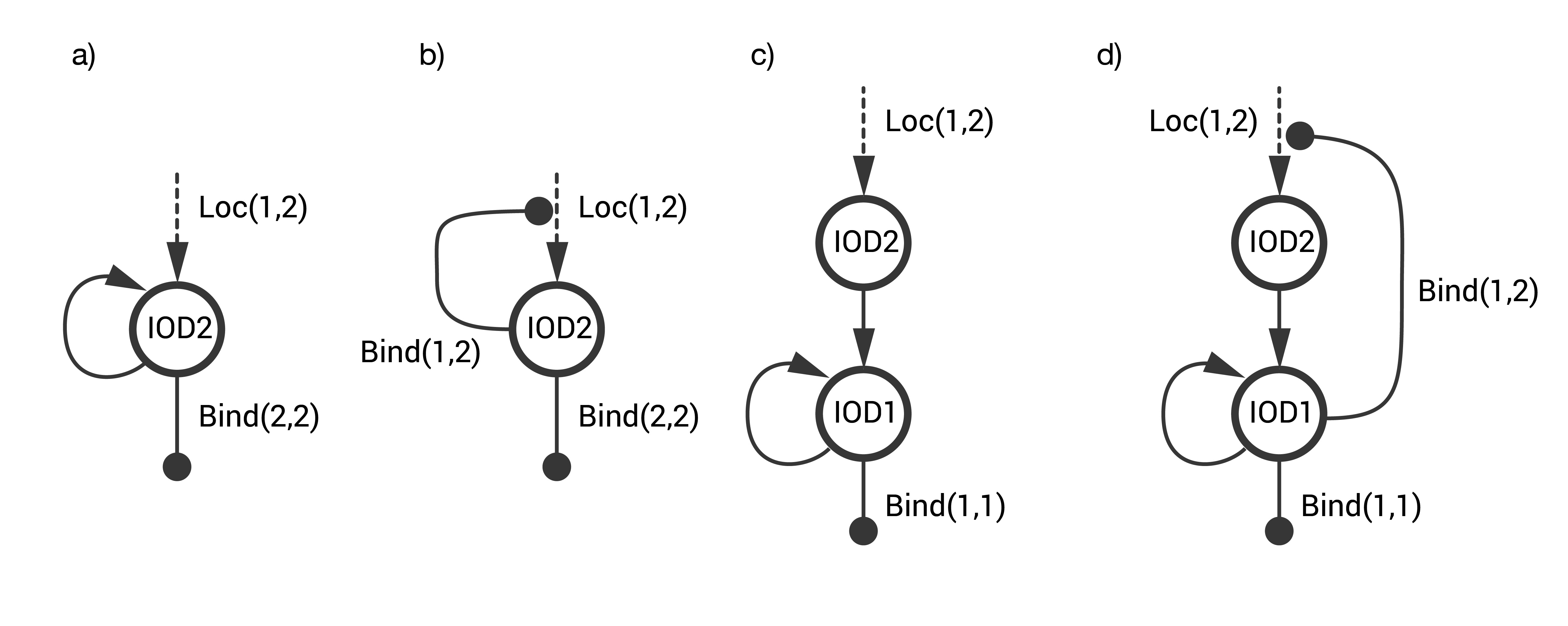
Several designs for the IOD band were explored. The goal was to design a STN that identifies a CTC with a unique combination of two surface markers without generating an off-target response, i.e., false positives that arise either spontaneously or on cells having only one of the two markers. The designs considered are combinations of three fundamental STNs (see below).
- STN(a) includes single step activation with positive auto-activation.
- STN(b) includes single step activation with positive autoregulation at the cell-cell level.
- STN(c) includes a two-step activation architecture with positive auto-activation.
The first two STNs proved to have a high rate of false positives. The final design STN(d) was a combination of STN(b) and STN(c).
The CeCe simulator
The CeCe simulation environment was developed to capture in one setting the key processes that influence cell-cell signal transmission. The underlying scene is a simple 2D world. Cells enter and exit this world through predefined channels of arbitrary shape. Each cell executes its own stochastic biochemical reactions and based on its state interacts with the rest of the population. As such, CeCe is easy to setup, intuitive to interprate, and fast to run.
In its interior CeCe integrates intracellular stochastic biochemical reactions with extracellular diffusion and cell movement including cell-cell interactions. Biochemical reactions are executed using the SSA algorithm. Streamlines for given channel topologies are computed using the Lattice-Boltzman method. Diffusion is computed efficiently using the analytical solution to the 2D diffusion equation with fixed volume point source. Hence CeCe simulator really combines the stochastic, continuous, discrete, and spatial phenomena that underlie signal transmission in cell populations. This was not an easy task as the numerical stability of each simulator component involves requirements on spatial and temporal granularity. For details on simulator implementation see Software.
Simulations results
The two component IOD band design represented by the signal transmission network STN(d) was tested in identifying a two marker (\(mar^1, mar^2\)) CTC profile. Within CeCe two negative and one positive scenarios were generated. A CTC candidate \(16\mu m\) in diameter was positioned in the center of a curved channel and given a constant number (1000 copies) of \(mar^1\), \(mar^2\) or both. The cell was free to rotate but remained in the same location through the entire simulation. An admissible IOD band design would only initiate cell clumping if both \(mar^1\) and \(mar^2\) are displayed.
Simulation start was marked by the introduction of the two types of IODs (IOD1 and IOD2) at a fixed density through the left channel entrance. For the duration of the simulation IODs were acted on by hydrodynamic forces causing collisions between IOD pairs and between single IODs and the CTC candidate. Signal transmission by 2D diffusion and IOD activation through stochastic chemical reactions proceeded according to the STN design. Hypothetically, a CTC candidate bearing both markers strengthens signal transmission between IOD1 and IOD2 making IOD activation more likely.
Simulation outcome is either true or false depending on whether or not clumping of cells was observed. Clumping of cells may occur around the CTC or elsewhere in the medium. A good IOD band design should lead to clumping only around the CTC candidate and only if the CTC candidate bears both markers. The outcome was quantified by tracking the number of active transcription factors in IOD2, which is responsible for initiating the clumping process.
A few notes are in order. The simulation study represents the most tasking environment that truly pushes the robustness limits of the IOD band system. The following are some of the presented challenges:
- Laminar flow maintains constant distance between cells for an extended period of time. Cells that start together stay together as if they were collocated on a CTC.
- Unidirectional flow tends to generate a layer of cells on the forefront of the CTC trapping cells that normally would remain suspended.
- Boolean signalling pathways lack temporal filtering functions capable of suppressing false positives in the case of erroneous binding.
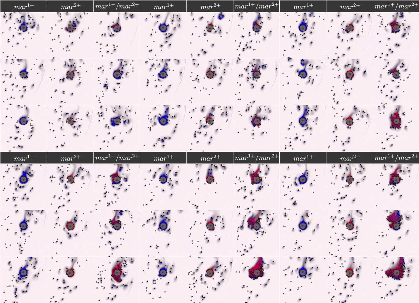
Below are the simulation results for the final design STN(d). The two sets of simulations to the left represent the two negative controls, \(mar^{1+}\) and \(mar^{2+}\), respectively. Three replicates are used for each. The rightmost simulation set demonstrates the positive test scenario where the CTC is \(mar^{1+}/mar^{2+}\). Clumping is clearly only present in the positive scenario.
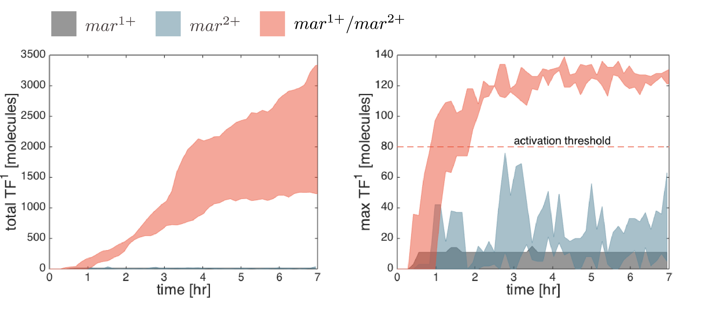
Simulation results are compared quantitatively below. The total number of active transcription factors in IOD1 (the IOD that initiate clumping in the designed STN(d)) is used to measure the IOD band response (the level of clumping observed in the above simulations). The total level of clumping (left figure) is proportional to the number of active transcription factors in all IOD1 cells. The clumping initiation time is best observed from the maximum number of active transcription factors per cell (\(TF_{max}=max_x(TF)\)) at any one time (see right figure). In all simulations, the activation threshold of transcription factors was unilaterally set to 80 copies. Hence the difference between \(TF_{max}\) and 80 copies represents the margin of safety for the negative controls or the margin of activation for the positive controls. Of the two negative controls, the \(mar^{1+}\) CTC candidate has a smaller margin of safety.
