Team:Cambridge-JIC/Stretch Goals
Screening System
The Concept
 To integrate OpenScope onto a desktop translation system (CNC), such as the Shapeoko, implementing an automated, high-throughput screening system for Enhancer Trap, Forward Mutagenesis and Reporter screens in Marchantia and potentially yeast. This involves sample scanning, detection and labelling, after macroscopic and microscopic imaging in brightfield and fluorescence.
The Approach
Using the CNC for coarse positioning (0.1mm accuracy) and OpenScope flexure-type plastic mechanisms for fine positioning (accuracy of the order of 1 μm). The Raspberry Pi camera is used for imaging. Exploit the image recognition software we have developed for labelling, and MicroMaps for image stitching to map the sample field. The original (unmodified) Raspberry Pi camera is used for macroscopic imaging, and the OpenScope optics cube (Raspberry Pi camera with inverted lens) - for microscopy.
Software Development
A Python driver script was written to control the Shapeoko. The code allows for a variety of actions: homing, positioning, collision feedback, speed control, path following, etc. The Webshell interface with OpenScope can be used for imaging and MicroMaps for processing.
Problems Encountered
Poor repeatability of CNC head positioning
Significant memory required for image storage
Full screening time of the order of 1 day
Theoretically, the calculations go as follows:
One image: 1024x768px, size on disk: approx. 400KB
Maximal reliable travel speed of Shapeoko head: 900cm/min
Field of view (Raspberry Pi camera with inverted lens, as in the OpenScope): approx. 50x40μm, hence area = 2000μm2=2x10⁻⁵cm2
Standard Petri dish: 90mm diameter, hence area ≈ 64cm2
Number of images required to cover whole Petri: 64cm2/2x10-5cm2≈3x106 images, i.e. 109 KB memory (approx. 1TB)
Time to scan whole area of 1 Petri: 17hrs at max speed (3x10⁶ squares with 50μm sides); in practice constant movement with maximal speed is not possible – the head needs to start/stop/focus, so the estimated time is 24hrs or more (but this might still be decreased by a faster moving head on a more reliable CNC)
In short, after doing this math, we almost gave up on the idea. However, after some more maths, we came up with a...
Solution
Preliminary scanning can be carried out with a macroscopic (normal) camera. The image recognition software can then scan for whole colonies or Marchantia plants within the recorded images. This turns out to be much more feasible:
Camera field of view: 3.5x2.5cm, hence area ≈ 8.5cm2
Images required to cover whole Petri dish: 64cm2/8.5cm2=8 images
Accounting for overlaps required for stitching at x4 coverage (each vertex appears in 4 neighbouring images), this gives 32 images
Total memory usage: 32 x 400KB ≈ 13 MB
This approach significantly reduces the number of images and time required to cover a whole plate. When image recognition software is implemented, it is possible to label areas of interest within the whole sample field. These specific areas can then be imaged by the microscope head attachment independently.
Software Architecture

We began to develop some python libraries to automatically manage this process, with an architecture as seen in the image to the right. The software in its current state is available within the 'lib' and 'hw' directories in our Github repository, which can be found on our downloads page (or go here to look for future revisions). It is based around a series of abstraction layers with the ultimate goal of hiding any underlying hardware and allowing easy automation of experiments. Our example use case focused on here is an automated screening system as described above whereby a macroscopic camera images a large sample set, software is then used to identify individual samples which are independently imaged by a microscopic camera, finally we screen these images using a range of image processing algorithms to identify different phenotypes. We can then select for these, e.g. by physically marking them, or even transferring them or destroying negative samples.
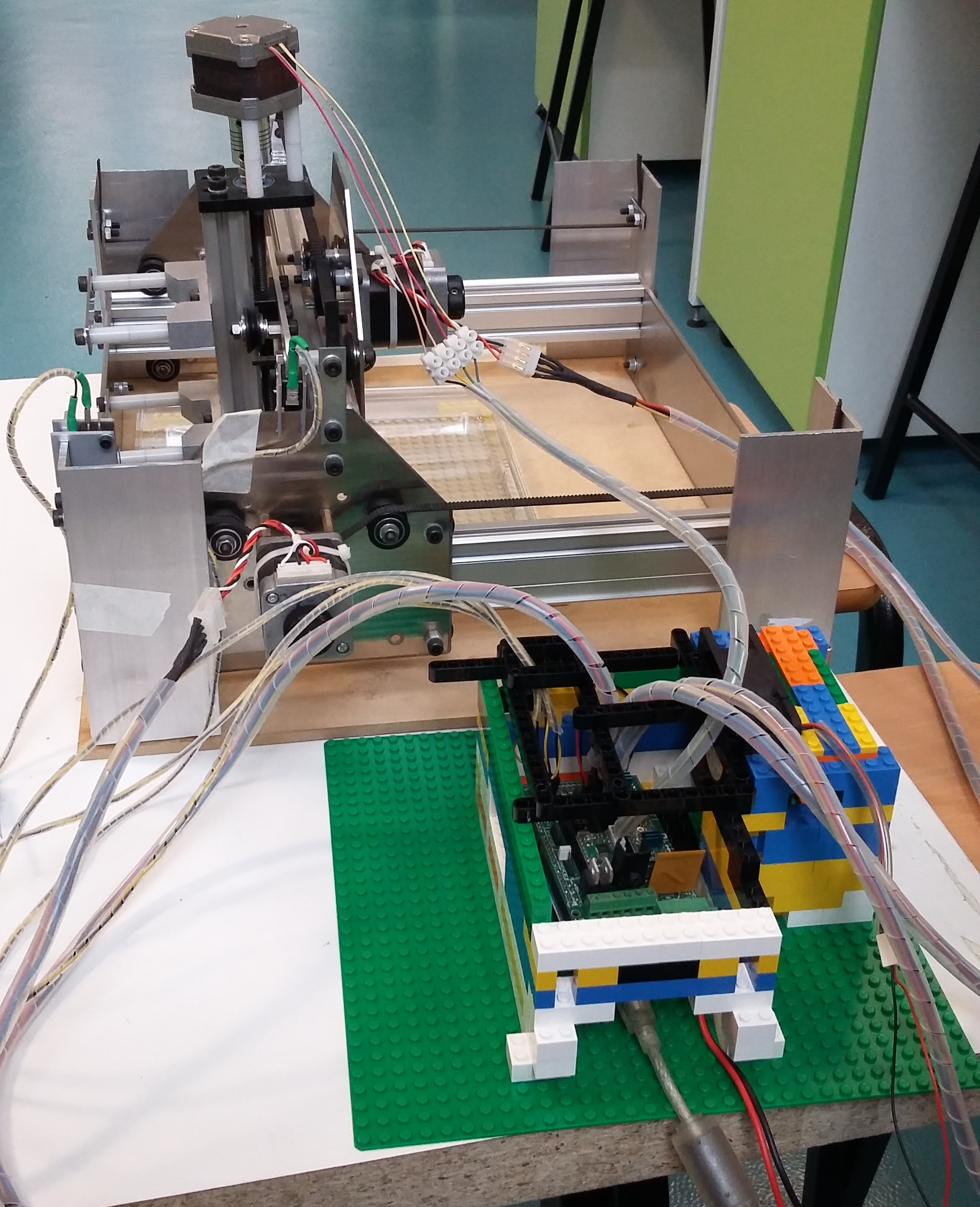
- We start with the hardware itself. An xyz translation system, such as a Shapeoko or other CNC machine, is fitted with at least one 'head'. The most important head for our use is our OpenScope microscope. In our example we would also fit the Shapeoko with a macroscopic camera (or an overhead camera with a sufficiently large field of view). Further, we intend to have a marker. There are multiple ways to switch out heads; one simple way is a turret-like rotational mechanism, as used to switch out objectives in a desktop microscope. Another might be a magnetic mechanism to pick up and drop heads in a specially allocated bay within the xy stage. Our libraries are sufficiently general that hopefully we can automate even more complicated experiments, such as by adding in a Gilson pipette head.
- The next layer up is the driver software which interacts directly with this hardware.
- The Shapeoko itself is controlled by an Arduino Mega with a G-code interpreter installed which we can interface with to send complex movement commands (such as precision arcs) and to recalibrate at any time. Our driver can handle unexpected events such as cable disconnection with ease, recalibrating afterwards in case of unaccounted-for interruptions.
- We anticipate that most other heads will be controlled by Arduinos (or a Raspberry Pi for the OpenScope camera, due to the high bandwidth requirements). The OpenScope software can be directly leveraged for the camera heads.
- In our calibration tests we attached a pen to the Shapeoko head. This was much simpler as we could control the z axis to apply the pen at will, without any additional arduinos to interface with.
- We also have some virtual hardware in our examples and tests to demonstrate the abilities of the software, such as a camera which can navigate a gigapixel image of the Andromeda galaxy
Proof of Concept (Experiment)
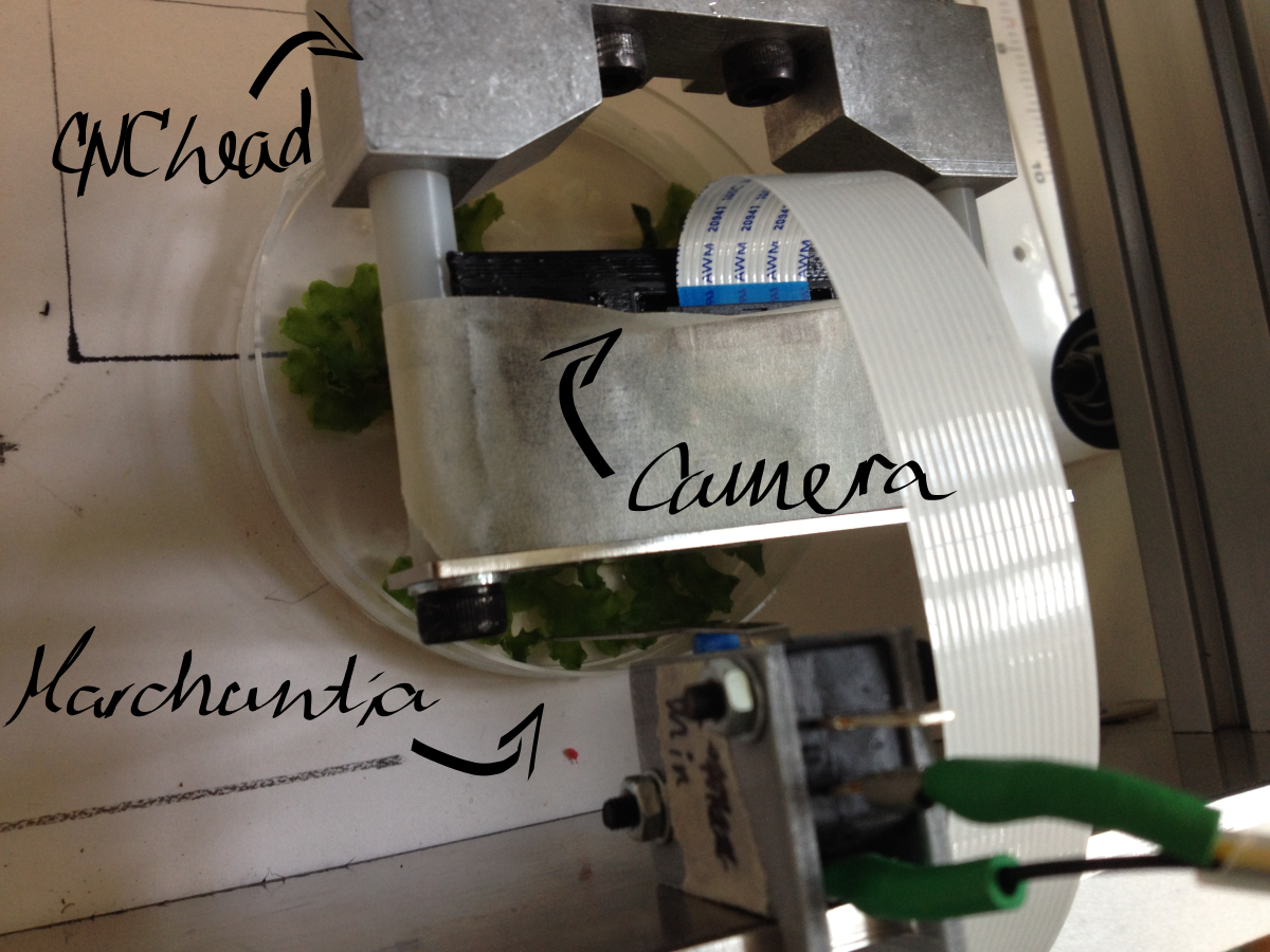
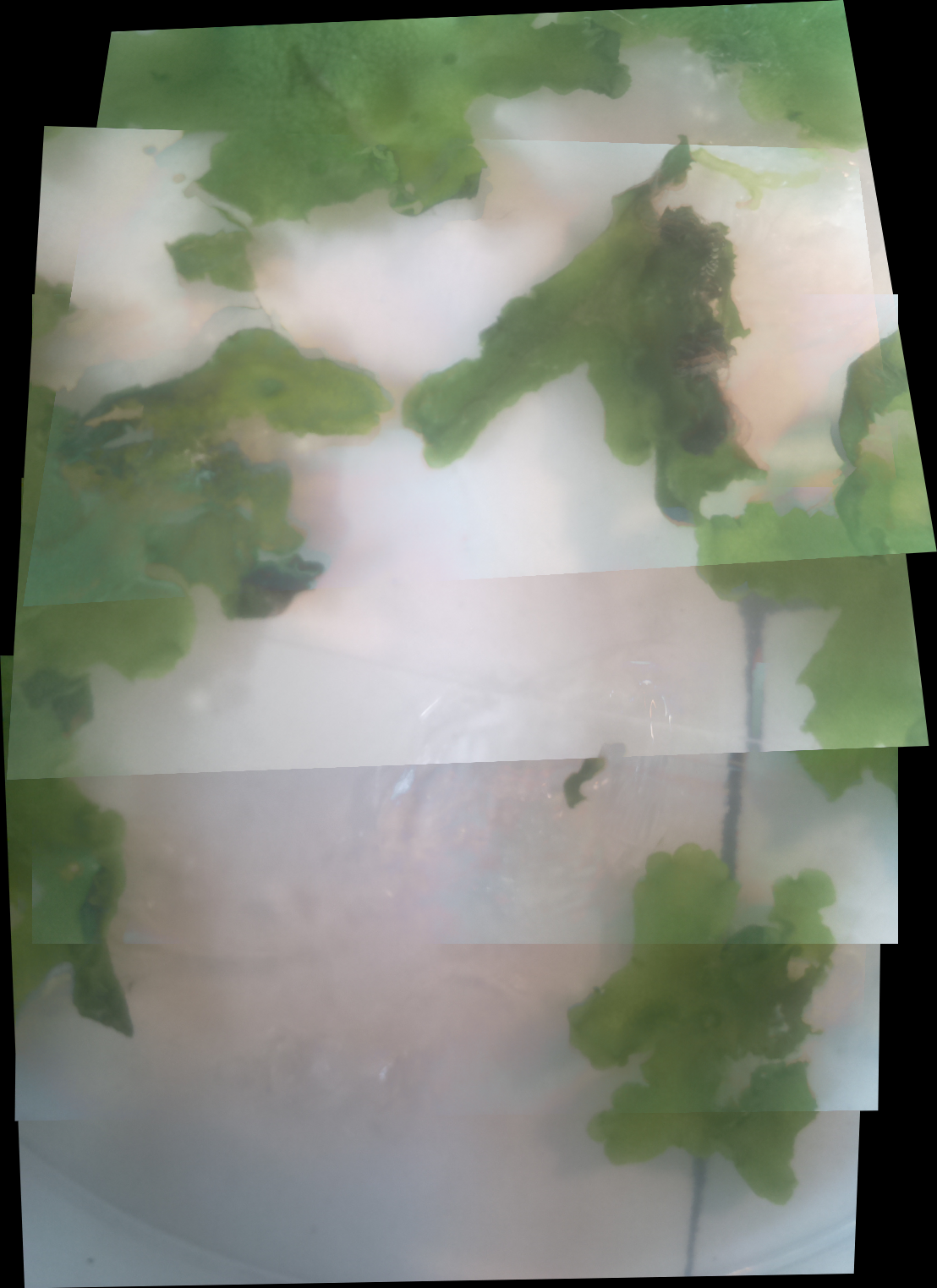
Macroscopic imaging of a Petri dish containing mature Marchantia samples was carried out. Images were captured manually through the Webshell during 1-2 minutes of operation. A Raspberry Pi camera was fixed to the CNC (in our case a Shapeoko v1, 150GBP second-hand) with a 3D-printed static mount. The motorised z-axis driven by the python program allowed for focusing of the sample. Seven images were successfully stitched, in a remarkable stitching time of 1.5sec. It is notable that the stitching algorithm copes well even with frames which are rotated at a small angle relative to each other.
Future opportunities
Incorporate of OpenScope onto the CNC head.
Develop colony screening for yeast/bacterial colonies on Petri dishes. Criteria such as distinct colour or fluorescence can be incorporated into the image recognition software. However, the fluorescence imaging achieved on OpenScope is not currently reliable enough to perform fluorescence screening.
Implement focus-stacking software for 3D samples (like Marchantia). This facilitates the development of programs which track the growth of samples.